Speed reducer output end sealing structure and RV speed reducer composed of same

A technology of sealing structure and output end, which is applied in the direction of mechanical equipment, transmission parts, belts/chains/gears, etc. It can solve the problems of shortened service life of glue, oil leakage, and inability to guarantee the sealing effect, so as to improve the service life of the seal and reduce the sealing effect. Difficulty of operation, effect of improving sealing performance

Active Publication Date: 2018-10-30
NANTONG ZHENKANG WELDING ELECTROMACHINERY +1
View PDF8 Cites 3 Cited by
  • Summary
  • Abstract
  • Description
  • Claims
  • Application Information

AI Technical Summary

Problems solved by technology

[0004] 1. If the amount of glue used is too large, it will easily cause the glue to be squeezed into the planetary wheel groove when installing the output end flange, which will affect the normal operation of the planetary wheel. If the amount of glue used is not enough, it will be extremely difficult to ensure that the glue is evenly coated On the end face of the output frame, especially the narrow end face between the planetary wheel groove and the edge of the end face of the output frame, oil leakage is very easy to occur, so the sealing effect cannot be guaranteed;
[0005] 2. If the plane sealant is used for sealing, when the reducer is operated at a high temperature for a long time at high speed, the service life of the glue will be greatly shortened, and the sealing effect cannot be guaranteed for a long time;
[0006] 3. When a layer of flat sealant is applied between the output tray and the output end flange, the two metal planes are in soft contact rather than hard contact, which will inevitably affect the running accuracy of the output end flange;
[0007] 4. The use of flat sealant not only increases the production cost of the robot, but also leads to low production efficiency of the robot manufacturer

Method used


Image

  • Speed reducer output end sealing structure and RV speed reducer composed of same
  • Speed reducer output end sealing structure and RV speed reducer composed of same
  • Speed reducer output end sealing structure and RV speed reducer composed of same

Examples


Embodiment 1

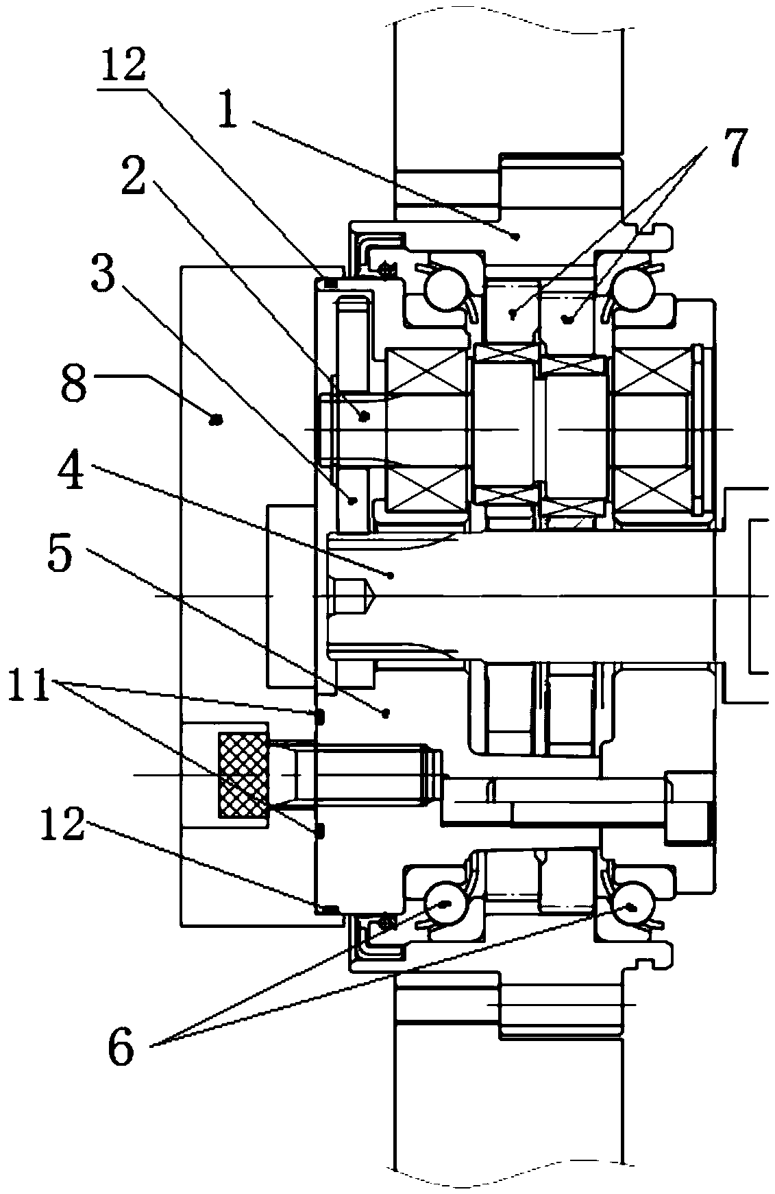
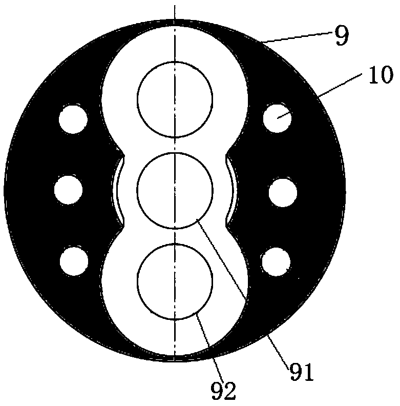
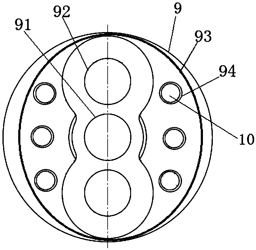
[0035] Such as figure 1 As shown, a sealing structure at the output end of a reducer includes an output end flange 8 and an output frame 5 connected to the reducer; the output frame 5 has a smooth output end face 9, and the center of the output end face 9 has a sun gear groove 91 And the planetary gear grooves 92 distributed axially symmetrically or annularly around the sun gear groove; the output end face 9 also has a threaded hole 10 for fixing the output disc frame 5, and the output end face 9 penetrates into the inside of the output end face flange 8 and is connected with the output The end flange 8 forms a face or line seal.

[0036] Such as figure 2 As shown, according to the sealing requirements, the black part in the figure is required to be sealed with the output end face flange 8, but the black part has a narrow edge, and it is required to apply neither too much nor too little glue, so the operation is extremely demanding, and The effect of sealing is not very ideal...

Embodiment 2

[0039] Such as figure 1 As shown, a sealing structure at the output end of a reducer includes an output end flange 8 and an output frame 5 connected to the reducer; the output frame 5 has a smooth output end face 9, and the center of the output end face 9 has a sun gear groove 91 And the planetary gear grooves 92 distributed axially symmetrically or annularly around the sun gear groove; the output end face 9 also has a threaded hole 10 for fixing the output disc frame 5, and the output end face 9 penetrates into the inside of the output end face flange 8 and is connected with the output The end flange 8 forms a face or line seal.

[0040] In this embodiment, at least one O-ring groove is formed on the outer wall of the output disk frame 5 on the output end face 9 in the radial direction, and the inner wall of the O-ring groove is provided for sealing the inner wall of the flange 8 on the output end face. The O-ring 12 on the outer wall of the output end surface 9 outputs the ...

Embodiment 3

[0044] Such as figure 1 As shown, an RV reducer with the sealing structure of the output end of the above-mentioned embodiment 1 or embodiment 2 includes a pin gear housing 1, an eccentric shaft 2, a planetary wheel 3, an input shaft 4, an output disc frame 5, and angular contact balls Bearing 6, cycloidal wheel 7, output end flange 8; planetary gear 3 is installed on one end of eccentric shaft 2; input shaft 4 is located in the center of pin gear housing 1, and the end gear of input shaft 4 and planetary gear 3 rotate at the same time Mesh connection on the plane constitutes the first-stage planetary deceleration mechanism; cycloid wheel 7, pin gear housing 1, and needle roller constitute the second-stage cycloid deceleration mechanism.

[0045] In addition, the eccentric shaft 2 of the RV reducer includes two cams 13, the axis lines of the two cams 13 are parallel to each other, and are symmetrically distributed on both sides of the main axis of the eccentric shaft 2 at 180°...


PUM


Abstract

The invention provides a speed reducer output end sealing structure and an RV speed reducer composed of the speed reducer output end sealing structure. The speed reducer output end sealing structure is characterized by comprising an output end face flange and an output disc rack; the output disc rack is provided with a smooth output end face, and the center of the output end face is provided witha sun wheel groove and planet wheel grooves distributed around the sun wheel groove in an axially symmetrical or annular manner; the output end face is further provided with threaded holes for fixingthe output disc rack, and the output end face stretches into the output end face flange and is in face sealing or linear sealing with the output end face flange. The RV speed reducer comprises a pin wheel housing, an eccentric shaft, a planet wheel, an input shaft, the output disc rack, angular contact ball bearings, cycloidal gears and the output end face flange. By means of the RV speed reducer,the installation difficulty of the output end face flange of users is greatly lowered, the users do not need to use a plane sealant for sealing, the cost is lowered, and efficiency is improved; and the oil sealing effect is better, and the operation precision is higher.

Description

technical field [0001] The invention relates to the technical field of precision reducers, in particular to a sealing structure for an output end of a reducer and an RV reducer formed thereof. Background technique [0002] RV reducer has the advantages of high rigidity, high precision, high bearing torque and high transmission efficiency, and is widely used in high-precision robot joints and high-precision transmission under heavy load conditions. figure 1 It is a simplified structural diagram of a traditional RV reducer. Both sides are open structures, and both sides need to be sealed when in use. One end of the input shaft is the central gear, which meshes with the planetary gear of the RV reducer to form a first-stage planetary reduction mechanism; the other end of the input shaft is connected to the servo motor. Cycloid wheel, needle roller and pin gear housing constitute the second stage cycloid reduction mechanism. The two-stage reduction mechanism is connected by an...

Claims


Application Information

Patent Timeline
Patent Type & Authority Applications(China)
IPC IPC(8): F16H57/029F16H57/021F16C3/18
CPCF16C3/18F16H57/021F16H57/029
Inventor 童彤顾京君莫会成朱利民梁得亮
Owner NANTONG ZHENKANG WELDING ELECTROMACHINERY
Why Eureka
Try Eureka