Boiler smoke waste heat recovering device and waste heat recovering method thereof

A waste heat recovery and boiler flue gas technology, which is applied in combustion methods, indirect heat exchangers, climate sustainability, etc., can solve the problem of ineffective cleaning of flue gas waste heat recovery device soot, etc., and achieve the effect of preventing people from scalding

Inactive Publication Date: 2018-10-30
芜湖乐知智能科技有限公司
View PDF6 Cites 5 Cited by
  • Summary
  • Abstract
  • Description
  • Claims
  • Application Information

AI Technical Summary

Problems solved by technology

[0004] However, the existing flue gas waste heat recovery device will accumulate a large amount of soot over time, which cannot effectively clean the soot in the flue gas waste heat recovery device

Method used


Image

  • Boiler smoke waste heat recovering device and waste heat recovering method thereof
  • Boiler smoke waste heat recovering device and waste heat recovering method thereof
  • Boiler smoke waste heat recovering device and waste heat recovering method thereof

Examples


Embodiment 1

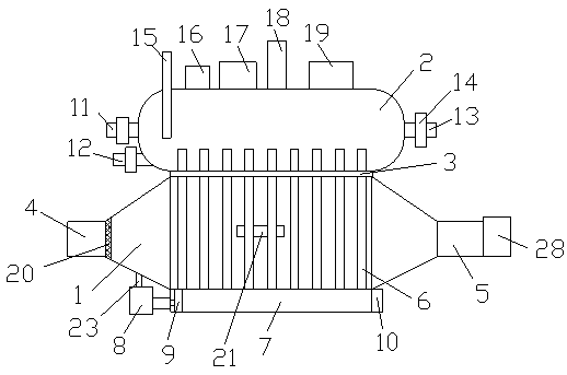
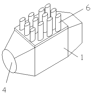
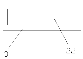
[0031] Such as figure 1As shown, a boiler flue gas waste heat recovery device includes a flue gas box 1 and a water tank 2, the water tank 2 is located above the flue gas box 1, and a partition 3 is arranged between the flue gas box 1 and the water tank 2, so Both the smoke box 1 and the water tank 2 are integrated with the partition 3, and the smoke box 1 is provided with an inlet pipe 4 for conveying smoke and an exhaust pipe 5 for discharging smoke. Both the air pipe 4 and the exhaust pipe 5 are in communication with the smoke box 1, and the intake pipe 4 and the exhaust pipe 5 are fixedly connected with the smoke box 1, and the inside of the smoke box 1 is provided with a gravity heat pipe for transferring heat 6. The gravity heat pipes 6 are arranged at equal intervals, one end of the gravity heat pipe 6 is bolted to the flue gas box 1, and the other end of the gravity heat pipe 6 is arranged through the partition 3 and the water tank 2. The gravity heat pipe 6 A soot ta...

Embodiment 2

[0034] Such as Figure 1-4 As shown, a boiler flue gas waste heat recovery device includes a flue gas box 1 and a water tank 2, the water tank 2 is located above the flue gas box 1, and a partition 3 is arranged between the flue gas box 1 and the water tank 2, so Both the smoke box 1 and the water tank 2 are integrated with the partition 3, and the smoke box 1 is provided with an inlet pipe 4 for conveying smoke and an exhaust pipe 5 for discharging smoke. Both the air pipe 4 and the exhaust pipe 5 are in communication with the smoke box 1, and the intake pipe 4 and the exhaust pipe 5 are fixedly connected with the smoke box 1, and the inside of the smoke box 1 is provided with a gravity heat pipe for transferring heat 6. The gravity heat pipes 6 are arranged at equal intervals, one end of the gravity heat pipe 6 is bolted to the flue gas box 1, and the other end of the gravity heat pipe 6 is arranged through the partition 3 and the water tank 2. The gravity heat pipe 6 A soo...


PUM


Abstract

The invention discloses a boiler smoke waste heat recovering device which comprises a smoke box and a water tank. The water tank is located above the smoke box. A partition plate is arranged between the smoke box and the water tank. The smoke box and the water tank are arranged integrally with the partition plate. The smoke box is provided with a gas input pipe used for conveying smoke, and an exhausting pipe used for exhausting the smoke. The gas input pipe and the exhausting pipe are fixedly connected with the smoke box. Gravity heat pipes used for transferring heat are arranged in the smokebox and are distributed at equal distances. The ends of the gravity heat pipes are in bolt connection with the smoke box. A soot groove used for piling soot is arranged under the gravity heat pipes.The soot groove is detachably connected with the smoke box. An electric cylinder is arranged on the left side of the soot groove. The electric cylinder is provided with a pushing plate. The pushing plate is in bolt connection with the electric cylinder. A soot opening used for discharging the soot is formed in the right side of the soot groove. The boiler smoke waste heat recovering device can effectively clear the soot.

Description

technical field [0001] The invention relates to a boiler flue gas waste heat recovery device and a waste heat recovery method. Background technique [0002] In the past ten years, due to the shortage of energy sources, with the further development of energy conservation work. A variety of new, energy-saving and advanced furnace types are becoming more and more perfect, and the use of high-quality insulation materials such as new refractory fibers has significantly reduced the heat dissipation loss of the furnace. The advanced combustion device is used to strengthen the combustion, reduce the amount of incomplete combustion, and the air-fuel ratio tends to be reasonable. However, the technology of reducing the heat loss of flue gas and recovering the waste heat of flue gas is still not progressing fast. In order to further improve the thermal efficiency of the kiln and achieve the purpose of saving energy and reducing consumption, recycling flue gas waste heat is also an im...

Claims


Application Information

Patent Timeline
IPC IPC(8): F23J15/06F23J3/00F28D15/02
CPCF23J3/00F23J15/06F28D15/0275Y02E20/30
Inventor 不公告发明人
Owner 芜湖乐知智能科技有限公司
Why Eureka
Try Eureka