Trigger control and state monitoring device for high-voltage thyristor and application method of trigger control and state monitoring device

A state monitoring device, high-voltage thyristor technology, applied in emergency protection circuit devices, output power conversion devices, electrical components, etc., can solve problems such as difficulty in obtaining energy for triggering and monitoring circuits, thyristors are in a conducting state, and cannot be separated separately. , the protection threshold value is convenient, the principle is simple and reliable, and the cost is low.

Active Publication Date: 2018-10-30
湖南省湘电试验研究院有限公司
View PDF8 Cites 4 Cited by
  • Summary
  • Abstract
  • Description
  • Claims
  • Application Information

AI Technical Summary

Problems solved by technology

Since the thyristor operates at a high potential, its trigger and monitoring design must solve technical problems such as high-voltage isolation, difficulty in obtaining energy from the circuit, and compatibility with strong interference electromagnetic environments.
Usually, photoelectric conversion technology is used to realize signal transmission and isolation of high potential. Traditional converter valve thyristor trigger and monitoring adopts five-pulse encoding method, and valve-based electronic equipment compiles pulses of five characteristic sequences and sends them to thyristor high potential board to realize triggering. , state monitoring, BOD protection monitoring and other functions, the pulse identification needs to be processed in a complex sequence, if the trigger pulse identification is incorrect, it may cause the thyristor to be in the conduction state all the time, resulting in commutation failure and other problems
The five-pulse encoding method is not suitable for the working condition where the thyristor is used as a switch for series compensation equipment because the trigger control and state monitoring are read in the same sequence of pulses, and the two cannot be separated separately.

Method used


Image

  • Trigger control and state monitoring device for high-voltage thyristor and application method of trigger control and state monitoring device
  • Trigger control and state monitoring device for high-voltage thyristor and application method of trigger control and state monitoring device
  • Trigger control and state monitoring device for high-voltage thyristor and application method of trigger control and state monitoring device

Examples


Embodiment Construction

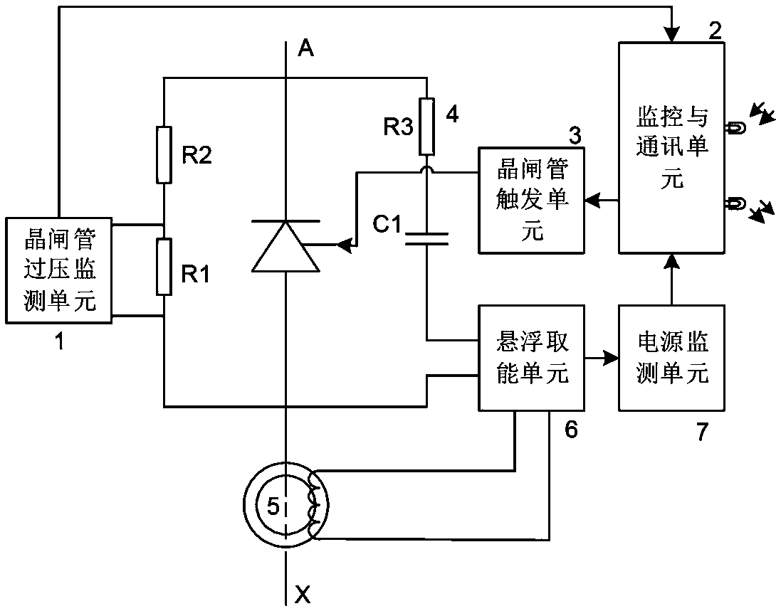
[0023] Such as figure 1 As shown, the high-voltage thyristor trigger control and state monitoring device in this embodiment includes a thyristor overvoltage monitoring unit 1, a monitoring and communication unit 2, a thyristor trigger unit 3, a resistance capacitance absorption circuit 4, an energy harvesting magnetic ring 5, and a suspension energy harvesting unit 6 And the power monitoring unit 7, the detection terminal of the thyristor overvoltage monitoring unit 1 is connected in parallel with the voltage dividing resistors at both ends of the monitored thyristor, the output terminal is connected to the monitoring and communication unit 2, and the control terminal of the thyristor trigger unit 3 is connected to the monitoring and communication unit 2 , the output end is connected to the gate of the thyristor to be monitored, the resistance-capacitance absorption circuit 4 is connected to the main circuit of the thyristor to be monitored, the energy-taking magnetic ring 5 is...


PUM


Abstract

The invention discloses a trigger control and state monitoring device for a high-voltage thyristor and an application method and device. The trigger control and state monitoring device comprises a thyristor overvoltage monitoring unit, a monitoring and communication unit, a thyristor trigger unit, a resistance-capacitance absorption unit, an energy-taking magnetic ring, a suspended energy-taking unit and a power supply monitoring unit, wherein an input end of the suspended energy-taking unit is connected with the resistance-capacitance absorption unit and the energy-taking magnetic ring separately; and the application method comprises the step that monitoring and trigger control are separately carried out on light-triggered pulses by adopting two modes of a single pulse and double pulses,and pulse coding is simple, so that the problem that the thyristor is always in a conducting state due to the fact that a pulse sequence formed by multiple continuous pulses is incorrect in identification is avoided. The trigger control and state monitoring device is simple, reliable and low in cost and can meet the thyristor triggering and monitoring requirements under different application conditions, and the functions of triggering, overvoltage protection and state monitoring for a single element of the thyristor at high potential or a valve bank are achieved.

Description

technical field [0001] The invention relates to electrical engineering technology, in particular to a high-voltage thyristor trigger control and state monitoring device and an application method thereof, which are used to realize functions such as triggering, overvoltage protection, and state monitoring of a high-potential thyristor single element or valve group. Background technique [0002] With the increasing application of high-power electronic devices in the power grid, a valve group composed of a single thyristor or multiple thyristors in series has appeared as a controllable power electronic switch, which is used in high-voltage environments, such as static var compensation devices. TCR valve group, series compensation bypass valve group, etc. In order to ensure the reliable operation of the thyristor, the state monitoring and control triggering of the thyristor are the key. Since the thyristor operates at a high potential, the design of its triggering and monitoring...

Claims


Application Information

Patent Timeline
Patent Type & Authority Applications(China)
IPC IPC(8): H02H7/20H02M1/06
CPCH02H7/205H02M1/06
Inventor 刘味果邱应军李娥英彭平
Owner 湖南省湘电试验研究院有限公司
Why Eureka
Try Eureka