Food cooking equipment

A cooking equipment, food technology, applied in the direction of household utensils, roasters/barbecue grids, utensils for frying things in oil, etc.

Pending Publication Date: 2018-11-02
FOSHAN SHUNDE KUFU ELECTRIC APPLIANCES CO LTD
View PDF9 Cites 13 Cited by
  • Summary
  • Abstract
  • Description
  • Claims
  • Application Information

AI Technical Summary

Problems solved by technology

[0007] Aiming at the defects of the prior art, the present invention provides a food cooker, which can reduce the problem of excessive exhaust gas temperature

Method used


Image

  • Food cooking equipment
  • Food cooking equipment
  • Food cooking equipment

Examples


Embodiment 1

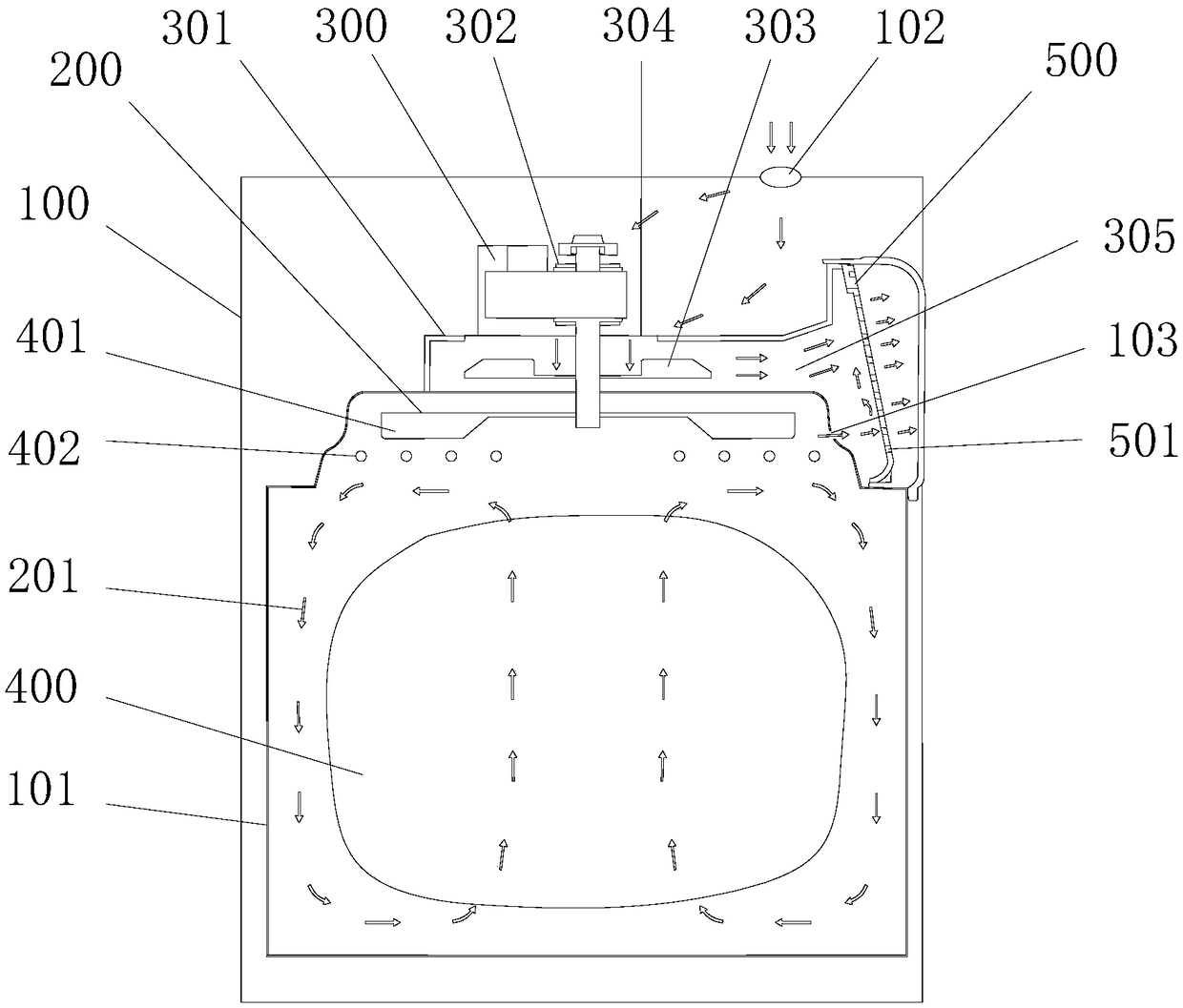
[0053] This embodiment provides a food cooking device, specifically a device for heating food by blowing high-temperature gas to the food, such as figure 1 As shown, it shows the working process of the air distribution device in the food cooking equipment, wherein the food cooking equipment includes: a casing 100, a hot air flow generating device 200 and a cold air flow device 300, specifically, the lower part of the inside of the casing The food cooking chamber 101 is provided at the position of the food cooking chamber 101, and the food cooking chamber 101 is used to heat the food 400 to be cooked. Preferably, the food 400 is placed in a drawer-type frying basket (or a rotating cage) for example, so as to evenly heat the food 400 .

[0054]The hot air flow generating device 200 is arranged on the top of the food cooking chamber 101, and it is used to generate a flowing hot air flow 201, and the generated hot air flow 201 can circulate in the food cooking chamber 101, constan...

Embodiment 2

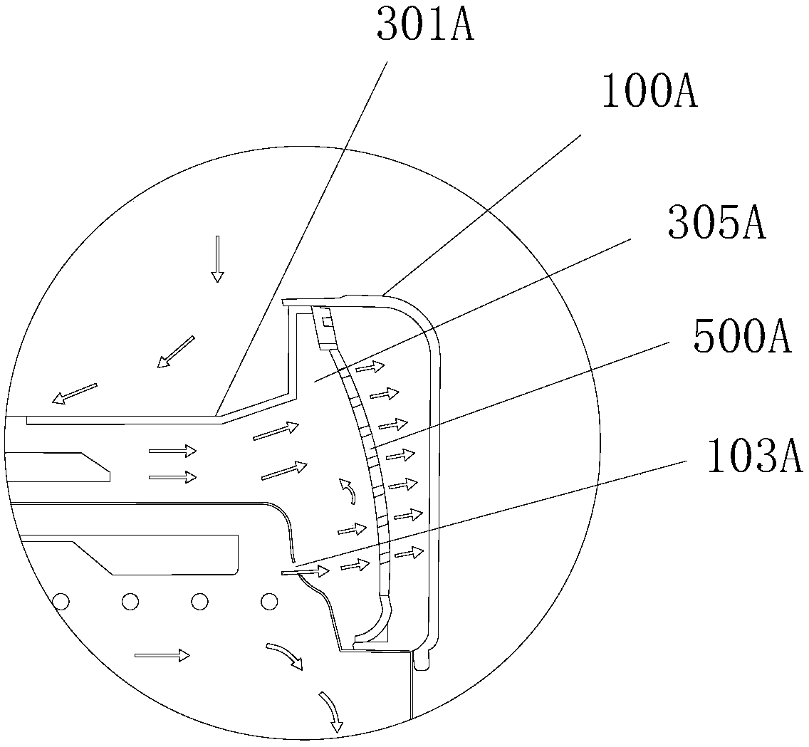
[0059] The difference between this embodiment and Embodiment 1 is that another air distribution device 500A is provided, such as figure 2 As shown, it specifically shows the working process of the high-temperature gas discharged from the water vapor outlet passing through the air distribution device 500A, wherein the air distribution device 500A completely covers the air discharge channel 305A, and the air distribution device 500A is along the direction of the gas in the air discharge channel. Flowing to the concave arc-shaped structure, the high-temperature gas discharged from the water vapor outlet 103A flows to the air distribution device 500A, a part of the high-temperature gas directly passes through the air distribution device 500A, and flows out to the outside of the housing 100A, and the other part of the high-temperature gas is in the air. Under the action of the flow distribution device 500A, the direction is changed to flow upwards, and it merges with the cold air f...

Embodiment 3

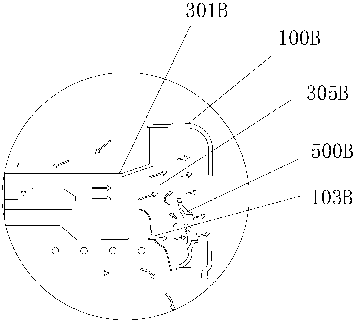
[0061] The difference between this embodiment and Embodiment 1 is that another air distribution device 500B is provided, such as image 3 As shown, it specifically shows the working process of the high-temperature gas discharged from the water vapor outlet passing through the air distribution device 500B, wherein the air distribution device 500B only partially covers the air discharge channel 305B, specifically, the air distribution device 500B completely covers the water vapor outlet 103B, and after the high-temperature gas discharged from the water vapor outlet 103B flows to the air distribution device 500B, almost all of the high-temperature gas changes direction and flows upward, and merges with the cold air flow discharged from the inside of the draft hood 301B to exchange heat After that, it passes through the air distribution device 500B and is discharged to the outside of the housing 100B.


PUM


Abstract

The invention provides food cooking equipment which comprises a shell and a cold air through-flow device. The shell is provided with a food cooking chamber, the cold air through-flow device comprisesan air drawing cover with an air drawing port, the air drawing cover is arranged in the shell and arranged on the upper portion of the food cooking chamber, the cold air through-flow device further comprises a motor and an air drawing wheel, the motor is arranged on the outer upper portion of the air drawing cover, the air drawing wheel is arranged inside the air drawing cover, the motor is arranged at the air drawing port and drives the air drawing wheel to rotate, the air drawing cover is provided with an air exhausting channel, the air drawing wheel drives air to flow towards the motor to form cold air flow, and the cold air flow flows into the air drawing cover through the air drawing port and is exhausted from the air exhausting channel. The food cooking chamber is provided with a water vapor exhaust port, the water vapor exhaust port is communicated with the air exhausting channel, and an air distribution device is arranged in the air exhausting channel and at the downstream of the water vapor exhaust port, so that part of high-temperature gas in the water vapor exhaust port changes in the flowing direction. The temperature of the exhausted gas can be effectively reduced.

Description

technical field [0001] The invention belongs to the field of home appliance manufacturing, and in particular relates to a food cooking device capable of reducing the temperature of exhaust gas. Background technique [0002] In the production process of fried food, frying pans are traditionally used for production, but there is a lot of oil fume in the use of frying pans, so they are used less and less in families; The application of the frying process has formed an air fryer, which uses fast-flowing hot air to heat the food. Compared with the traditional fryer, it can reduce 80% of the oil. It is easy to clean, safe and economical in household use. It has won the favor of consumers and has been widely developed. [0003] For example, a smokeless air fryer disclosed in Chinese patent document 201310101037.9 specifically includes an air fryer fixed body and an air fryer mobile body. There is a top-action power switch, and the upper end of the handle on the upper end of the a...

Claims


Application Information

Patent Timeline
Patent Type & Authority Applications(China)
IPC IPC(8): A47J37/12A47J37/06
CPCA47J37/06A47J37/1266A47J37/1271
Inventor 程晓梁福林肖丙三
Owner FOSHAN SHUNDE KUFU ELECTRIC APPLIANCES CO LTD
Why Eureka
Try Eureka