
Lifting device for construction engineering

A technology for construction engineering and placing racks, which is applied to portable lifting devices, hoisting devices, transportation and packaging, etc. It can solve the problems of high work intensity, potential safety hazards and inconvenience of moving personnel, and reduce work intensity and improve handling efficiency. , the effect of easy handling

Inactive Publication Date: 2018-11-02
湖州翔润化工有限公司
View PDF1 Cites 6 Cited by
  • Summary
  • Abstract
  • Description
  • Claims
  • Application Information

AI Technical Summary

Problems solved by technology

[0002] With the rapid development of society, the use of mechanical equipment has become more and more extensive. In the construction process of construction projects, construction materials need to be transported, and various equipment of construction machinery are required. The current construction projects are for Some construction materials are usually transported manually. However, due to the particularity of construction projects, it is often necessary to transport building materials from low places to high places. It is very inconvenient to use manual transportation of building materials, and the transportation efficiency is extremely low. The work intensity is high, time-consuming and labor-intensive, and building materials are prone to fall during the handling process of the staff, which poses hidden dangers to the safety of the handling personnel. At the same time, the height of most crane transportation equipment cannot be adjusted to transport materials, which has relatively limited limitations. Big

Method used

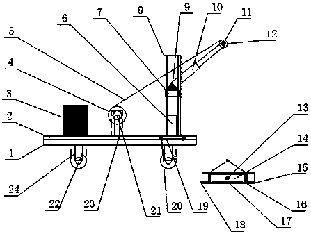

Image

  • Lifting device for construction engineering
  • Lifting device for construction engineering
  • Lifting device for construction engineering

Examples


Embodiment Construction

[0019] The following will clearly and completely describe the technical solutions in the embodiments of the present invention with reference to the accompanying drawings in the embodiments of the present invention. Obviously, the described embodiments are only some, not all, embodiments of the present invention. Based on the embodiments of the present invention, all other embodiments obtained by persons of ordinary skill in the art without making creative efforts belong to the protection scope of the present invention.

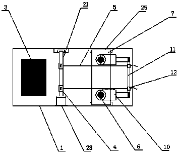
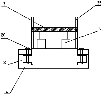
[0020] see Figure 1~4 , in an embodiment of the present invention, a lifting device for construction engineering, including a base 1, a chute 2, a counterweight 3, a winch 4, a cable 5, a hydraulic cylinder 6, a support plate 7, a support frame 8, and a mounting seat 9. Hydraulic cylinder 2 10, rotating shaft 2 11, fixed pulley 12, bolt 13, splint 14, hook 15, chute 3 16, cargo rack 17, tightening belt 18, slider 19, fastening screw 20, rotating shaft 1 21. ...


PUM


Abstract

The invention discloses a lifting device for construction engineering. A motor is fixedly mounted on a base through a motor mounting seat, the output end of the motor is connected with a first rotating shaft through a coupling, and winches are arranged on and connected with the first rotating shaft through keys; first hydraulic cylinders are fixedly arranged on a sliding block, a supporting frameis arranged on the two sides of the sliding block, a second sliding groove is formed in the supporting frame in the vertical direction, a supporting plate is in sliding connection within the second sliding groove in the supporting frame, and piston rods of the first hydraulic cylinder are connected with the lower bottom surface of the supporting plate by welding; and a cargo storing frame is of arectangular structure, stop blocks are symmetrically arranged on the two rectangular sides of the cargo storing frame, the stop blocks are arranged on the cargo storing frame by welding, third slidinggrooves are further formed in the cargo storing frame, clamping plates are in sliding connection within the third sliding grooves in the cargo storing frame, and a tightening belt and a hook are arranged on the other corresponding two sides of the cargo storing frame respectively.

Description

technical field [0001] The invention relates to the technical field of construction engineering, in particular to a lifting device for construction engineering. Background technique [0002] With the rapid development of society, the use of mechanical equipment has become more and more extensive. In the construction process of construction projects, construction materials need to be transported, and various equipment of construction machinery are required. The current construction projects are for Some construction materials are usually transported manually. However, due to the particularity of construction projects, it is often necessary to transport building materials from low places to high places. It is very inconvenient to use manual transportation of building materials, and the transportation efficiency is extremely low. The work intensity is high, time-consuming and labor-intensive, and building materials are prone to fall during the handling process of the staff, whi...

Claims


Application Information

Patent Timeline
Patent Type & Authority Applications(China)
IPC IPC(8): B66D3/20B66D3/26B66C1/44
CPCB66D3/20B66C1/445B66D3/26
Inventor 唐红娟
Owner 湖州翔润化工有限公司
Learn More