
Evaporation device and evaporation method

A technology for vapor deposition and vapor deposition materials, which is applied in the directions of vacuum evaporation coating, sputtering coating, ion implantation coating, etc., can solve the problems of uneven heating of vapor deposition materials, waste of vapor deposition materials, and blockage of openings, etc. Achieve the effect of reducing radial temperature difference, improving utilization rate, and improving heating uniformity

Active Publication Date: 2018-11-02
TCL CHINA STAR OPTOELECTRONICS TECH CO LTD
View PDF9 Cites 5 Cited by
  • Summary
  • Abstract
  • Description
  • Claims
  • Application Information

AI Technical Summary

Problems solved by technology

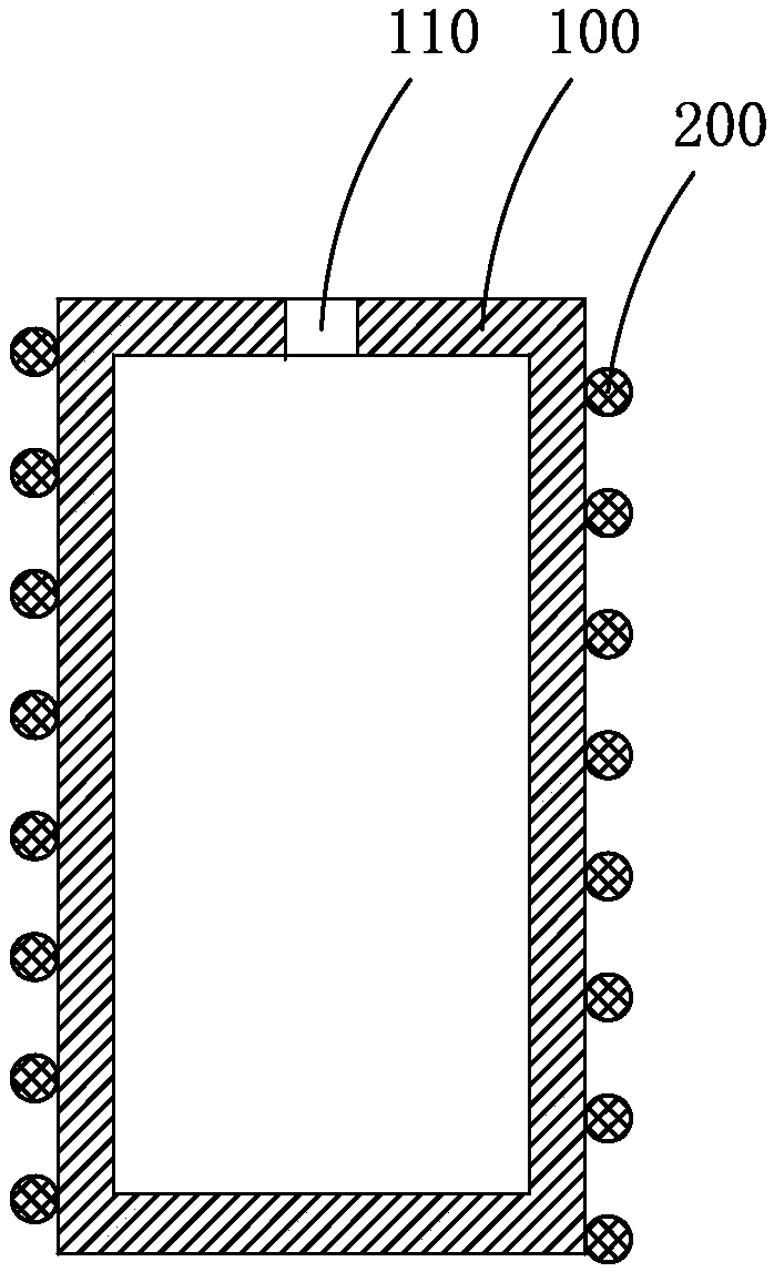
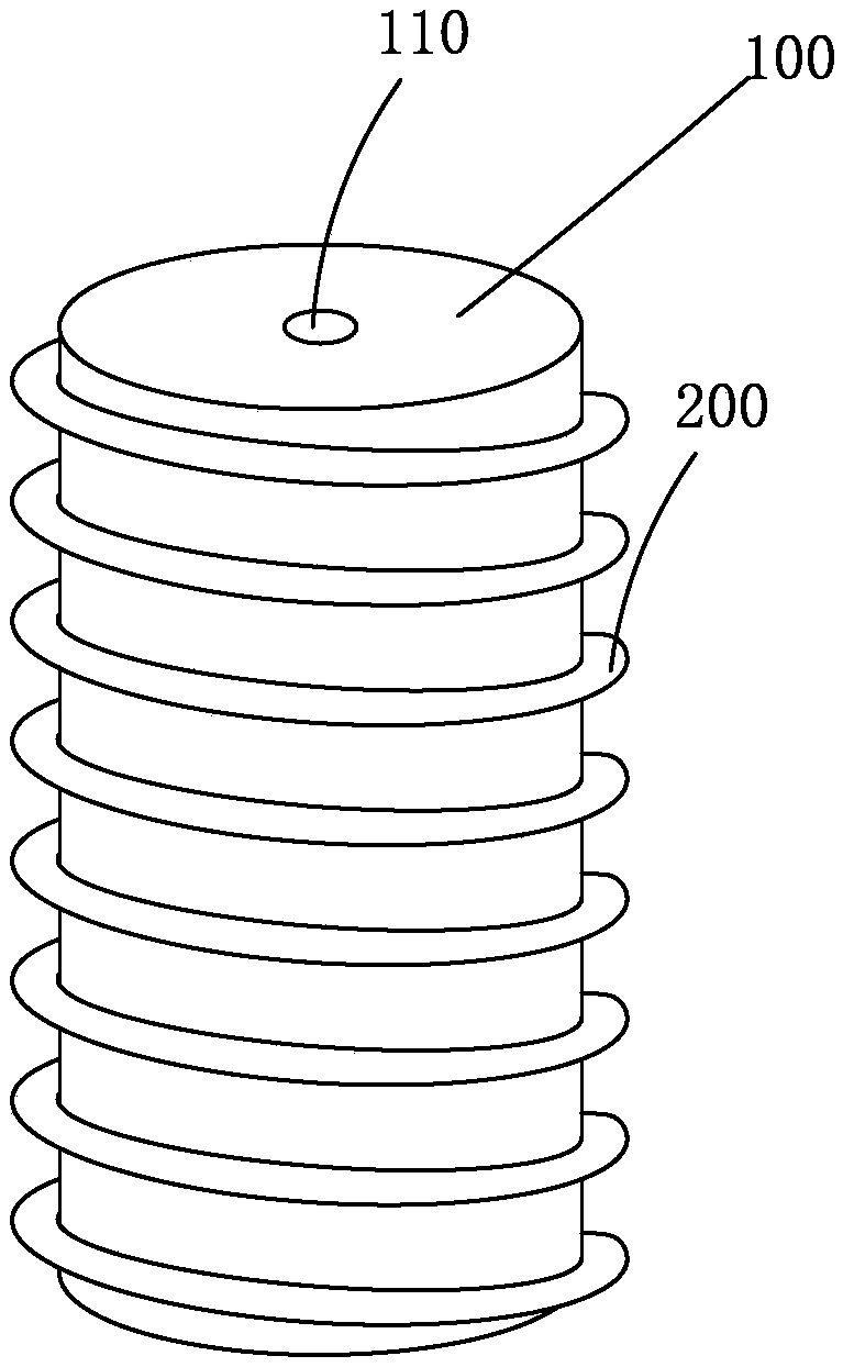
Since the evaporation material is generally a non-good conductor of heat, the crucible body 100 has a temperature difference in its radial direction when heated, and the temperature in the area closer to the axis of the crucible body 100 is lower, which will cause the evaporation material located in the crucible body 100 to be heated. Uneven, clogging the opening
At the same time, due to the need to maintain a stable rate at which the evaporation material is discharged from the opening 110 at the top of the crucible body 100, it is necessary to give priority to ensuring the temperature at the opening 110. Therefore, the crucible body 100 will also have a temperature difference in the axial direction. The temperature at the top of the crucible body 100 is higher than the temperature at the bottom, which makes the vapor deposition material at the bottom of the crucible body 100 reach the evaporation temperature, and when it passes through the top area of ​​the crucible body 100, its temperature will exceed the cracking temperature of the material and crack, resulting in this Part of the evaporation material is wasted

Method used


Image

  • Evaporation device and evaporation method
  • Evaporation device and evaporation method
  • Evaporation device and evaporation method

Examples


no. 1 example

[0068] see Figure 13 , and combined with Figure 14 and Figure 15 , the first embodiment of the evaporation method of the present invention is applied to the first embodiment of the above-mentioned evaporation device, including the following steps:

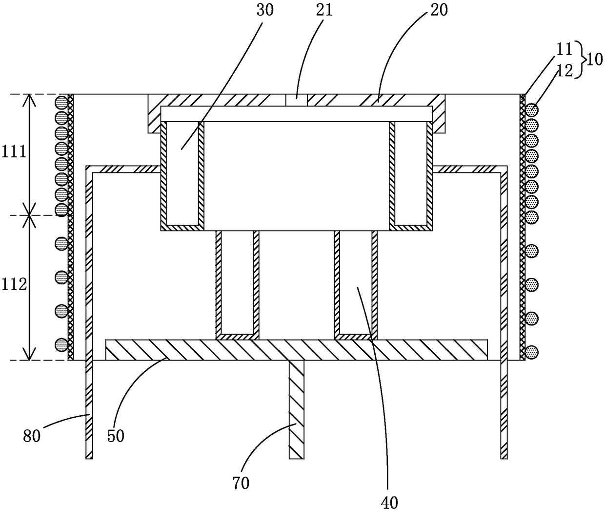
[0069] Step S1, please refer to Figure 14 , the evaporation material 1 is placed in the first crucible 30 and the second crucible 40 , and the moving part 50 is moved by the rod part 70 so that the second crucible 40 is located under the first crucible 30 .

[0070] Step S2, energize the heating wire 12, the heating wire 12 heats the evaporation material 1 in the first crucible 30 to evaporate and discharge it through the opening 21, and at the same time, the heating wire 12 heats the evaporation material 1 in the second crucible 40 warm up.

[0071] Specifically, since the density of the heating wire 12 in the first region 111 is greater than that in the second region 112, when the same amount of electricity is supplied, t...


PUM


Abstract

The invention provides an evaporation device and an evaporation method. The evaporation device comprises a heating source, a crucible cover, a first crucible, a second crucible, a moving part and a support, wherein the first crucible, the second crucible and the moving part are arranged below the crucible cover, and the first crucible is fixed on the support; the first crucible and the second crucible each comprise an inner side wall, an outer side wall and a bottom surface, the outer side walls are arranged outside the inner side walls, the bottom surfaces are connected with the inner side walls and the outer side walls, far away from one end of the crucible cover, the crucible cover is arranged on the outer side wall of the first crucible, the second crucible is fixed to the top surfaceof the moving part, the projection of the inner side wall of the first crucible in the vertical direction is located outside the outer side wall of the second crucible, and the density of an electricheating wire of a heating source in a first area corresponding to the position where the crucible cover and the first crucible are located is larger than the density of a second area below the first area. According to the evaporation device, the utilization rate of evaporation materials can be effectively improved, the radial temperature difference in the evaporation device can be effectively reduced, and the heating uniformity of the evaporation materials in the evaporation device is improved.

Description

technical field [0001] The invention relates to the technical field of display device manufacturing, in particular to an evaporation device and an evaporation method. Background technique [0002] Flat panel display devices have many advantages such as thin body, power saving, and no radiation, and have been widely used. Existing flat panel display devices mainly include liquid crystal display devices (Liquid Crystal Display, LCD) and organic electroluminescent display devices (Organic Light Emitting Display, OLED). Among them, compared with LCD, OLED display devices not only have excellent display performance, but also have all-solid-state, self-luminous, simple structure, ultra-thin, fast response, wide viewing angle, room temperature operation, low power consumption and easy realization of flexible display. And 3D display and other advantages, known as "dream display", unanimously recognized as the mainstream technology of next-generation display, and has been favored by...

Claims


Application Information

Patent Timeline
Patent Type & Authority Applications(China)
IPC IPC(8): C23C14/26C23C14/54H01L51/56
CPCC23C14/26C23C14/54H10K71/00
Inventor 匡友元
Owner TCL CHINA STAR OPTOELECTRONICS TECH CO LTD
Learn More