
Prefabricated protection slope structure and construction method thereof

A construction method and slope technology, applied in infrastructure engineering, excavation, construction, etc., can solve the problems of unguaranteed quality of cast-in-place joints, cumbersome construction procedures, low construction efficiency, etc., and achieve low cost and smooth construction process Simple, simple process effect

Active Publication Date: 2018-11-02
亓新广
View PDF11 Cites 6 Cited by
  • Summary
  • Abstract
  • Description
  • Claims
  • Application Information

AI Technical Summary

Problems solved by technology

[0003] The slope lattice frame is a common slope protection structure. There are two main construction methods for the traditional slope lattice frame: the first one is to use the cast-in-place construction method. The disadvantage of this method is that the cast-in-place slope lattice frame At the same time, scaffolding needs to be erected, the construction cost is high, and the construction efficiency is low; the second is the construction method of prefabricated installation. To form each prefabricated concrete rod as a whole, it needs to go through prefabrication, installation and cast-in-place processes, the construction process is cumbersome, and the quality of cast-in-place joints cannot be guaranteed

Method used


Image

  • Prefabricated protection slope structure and construction method thereof
  • Prefabricated protection slope structure and construction method thereof
  • Prefabricated protection slope structure and construction method thereof

Examples


Embodiment Construction

[0036] Embodiments of the technical solutions of the present invention will be described in detail below with reference to the accompanying drawings. The following examples are only used to illustrate the technical solutions of the present invention more clearly, and are therefore only used as examples, and cannot be used to limit the protection scope of this patent.

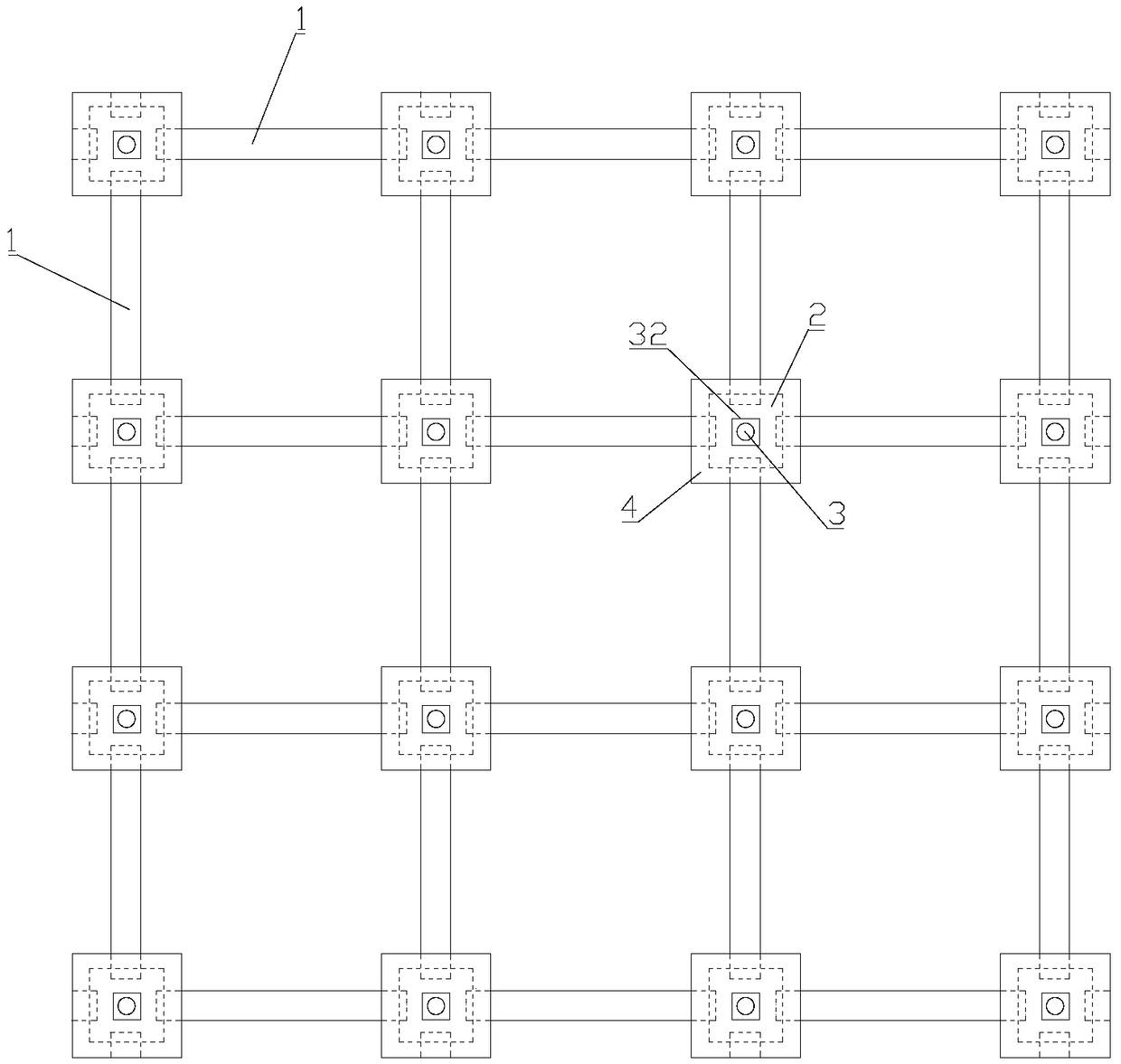
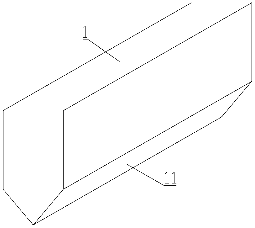
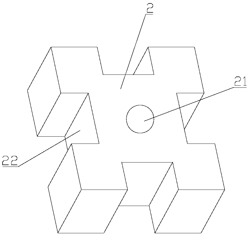
[0037] On the one hand, if Figure 1-Figure 5 As shown, the embodiment of the present invention provides a prefabricated slope protection structure, comprising: a soil retaining lattice frame, the soil retaining lattice frame is composed of a plurality of prefabricated lattice beams 1 crisscrossed, and the soil retaining lattice frame is installed on the slope; Several prefabricated connectors 2 at the junctions of each prefabricated lattice beam 1, the middle of the prefabricated connectors 2 is provided with a first through hole 21, and each prefabricated connector 2 is correspondingly provided with an anchor ...


PUM


Abstract

The invention discloses a prefabricated protection slope structure and a construction method thereof. The prefabricated protection slope structure comprises a soil retaining case frame, prefabricatedconnectors and prefabricated connecting caps. The soil retaining case frame is composed of prefabricated case frame beams. A first through hole is formed in the middle portion of each prefabricated connector. Each prefabricated connector is tensioned onto a slope surface though an anchor rod penetrating through the corresponding first through hole. Connecting clamping grooves are formed in the periphery of each prefabricated connector. The ends of each prefabricated case frame beam are embedded into the corresponding connecting clamping grooves. The lower side of each prefabricated connectingcap is provided with a groove. The four sides of each groove are provided with openings used for receding the prefabricated case frame beams. A second through hole is formed in the middle portion of the groove bottom of each groove. An anchor rod penetrates through the corresponding through hole. A net abutting against the outer side face of the corresponding prefabricated connecting cap is in threaded connection with each anchor rod. The prefabricated protection slope structure provided by the invention is high in construction efficiency, low in cost and more stable in structure.

Description

technical field [0001] The invention relates to the technical field of construction engineering, in particular to a prefabricated slope protection structure and a construction method thereof. Background technique [0002] In engineering construction, there are often a large number of excavation and filling, which form a large number of exposed slopes. The exposed slopes are likely to cause disasters such as soil erosion, landslides, and debris flows. Therefore, it is necessary to protect the exposed slopes. [0003] Slope trellis is a common slope protection structure. There are two traditional construction methods for slope trellis. The first is to use the cast-in-place construction method. When it is necessary to set up scaffolding, the construction cost is high and the construction efficiency is low; the second is the construction method of prefabricated installation. At present, the prefabricated slope lattice frame is usually reserved by prefabricated concrete rods. To...

Claims


Application Information

Patent Timeline
IPC IPC(8): E02D17/20
CPCE02D17/20E02D17/205
Inventor 亓新广亓一凡
Owner 亓新广
Learn More