Micro-foam double-machine co-extrusion three-layer square-grid building formwork

A technology of building formwork and micro-foaming, which is applied to buildings, building structures, formwork/formwork components, etc., can solve the problems of troublesome connection, affecting the dimensional accuracy of concrete structures, and reducing the deformation resistance of building formwork.

Pending Publication Date: 2018-11-02
苏州利波紧固件有限公司
View PDF0 Cites 0 Cited by
  • Summary
  • Abstract
  • Description
  • Claims
  • Application Information

AI Technical Summary

Problems solved by technology

[0002] Today's building formwork is widely used in the construction industry. In the process of preparing concrete structures, building formwork plays a key role. However, today's building formwork has the following problems: First, in order to save materials, it is generally used in building formwork. A hollow structure is added inside, and this hollow structure is often blocked by flowing mud. The hardening of the mud will reduce the deformation resistance of the building formwork, increase the weight of the building formwork, and increase the workload of the carrier; the second is be...

Method used


Image

  • Micro-foam double-machine co-extrusion three-layer square-grid building formwork
  • Micro-foam double-machine co-extrusion three-layer square-grid building formwork
  • Micro-foam double-machine co-extrusion three-layer square-grid building formwork

Examples


Embodiment Construction

[0019] The following will clearly and completely describe the technical solutions in the embodiments of the present invention with reference to the accompanying drawings in the embodiments of the present invention. Obviously, the described embodiments are only some, not all, embodiments of the present invention. Based on the embodiments of the present invention, all other embodiments obtained by persons of ordinary skill in the art without creative efforts fall within the protection scope of the present invention.

[0020] The specific implementation manner of the present invention will be further described in detail below in conjunction with the schematic diagrams.

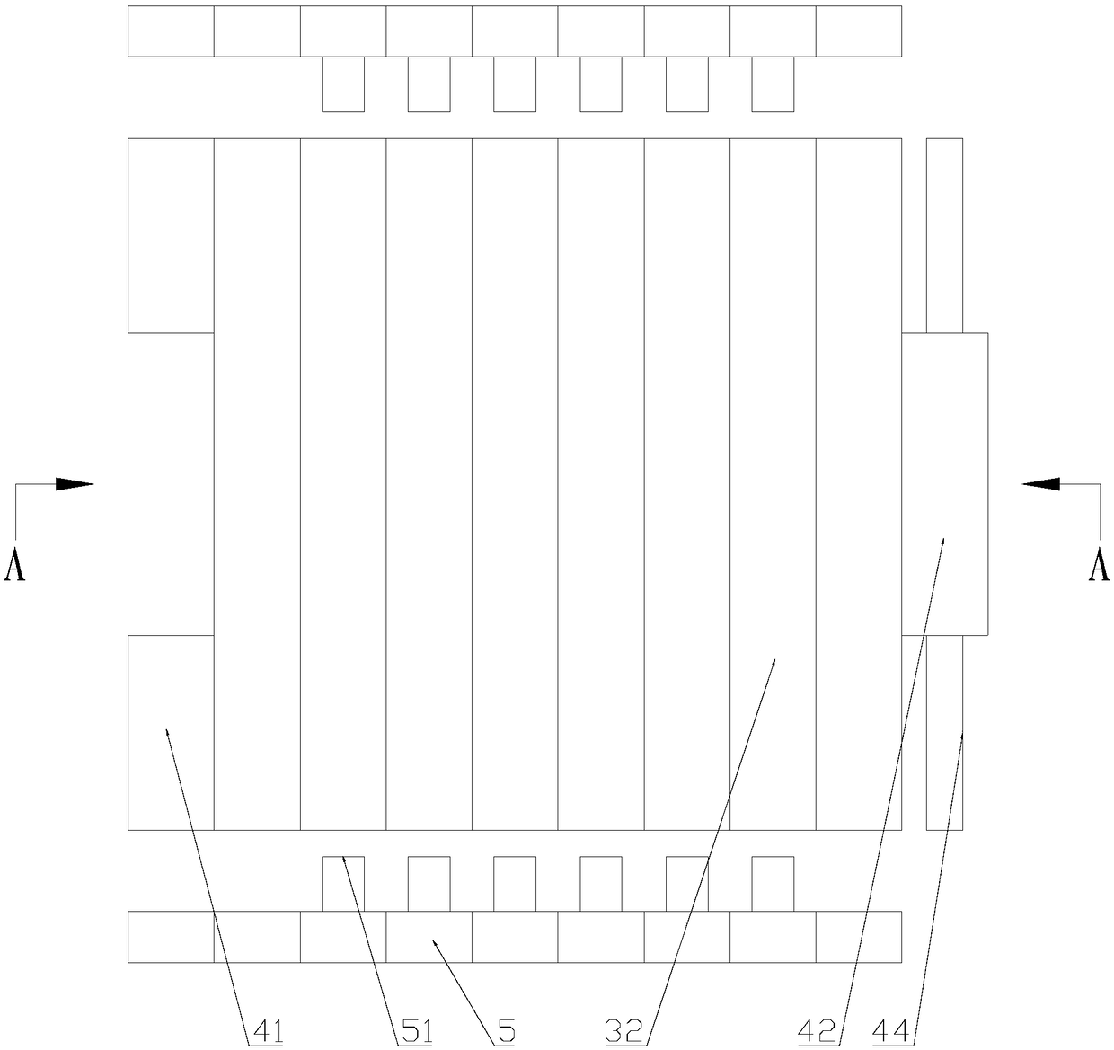
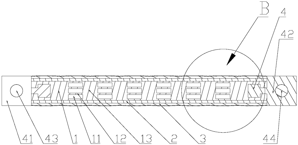
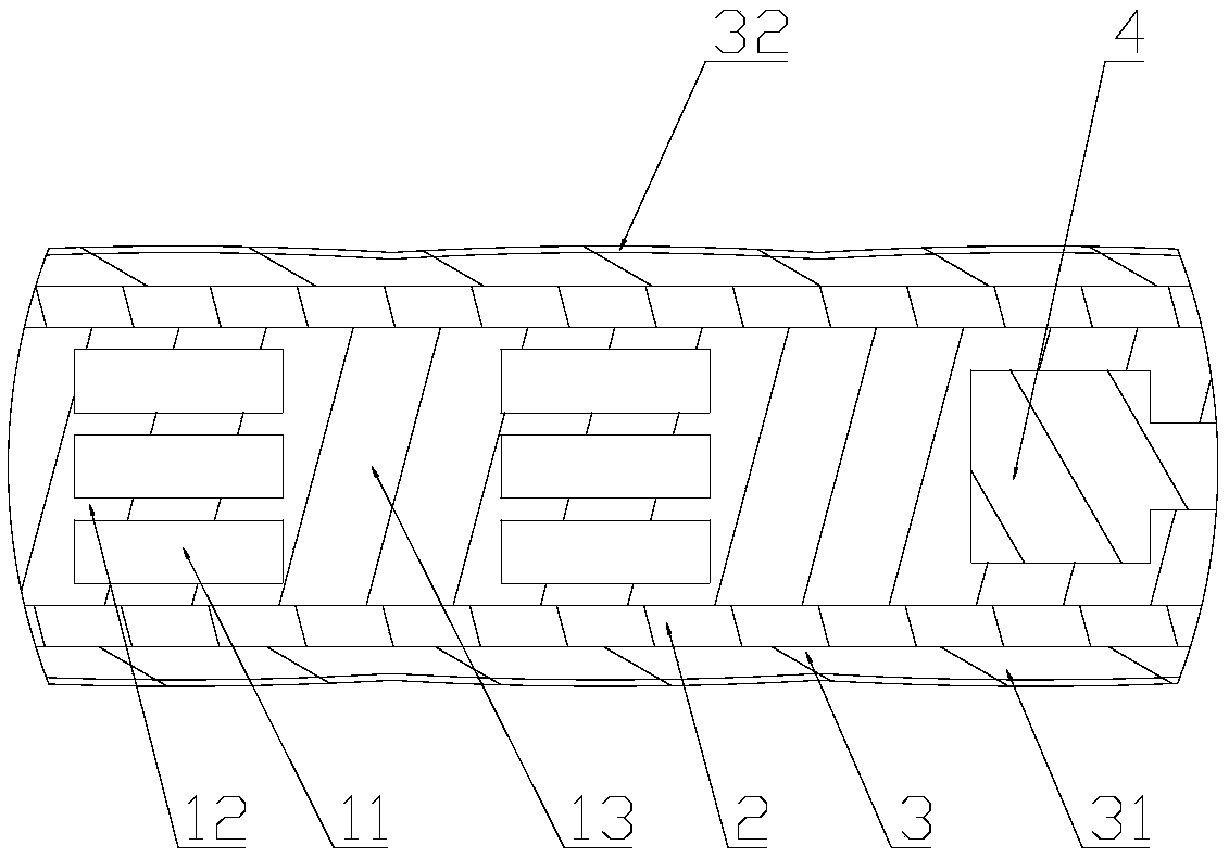
[0021] Such as figure 1 , figure 2 and image 3 As shown, a micro-foaming double-machine co-extruded three-layer square building formwork includes a substrate 1, a rectangular hollow channel 11 is provided in the substrate 1, and horizontal plates 12 and The vertical plate 13, the horizontal plate 12 and the ...


PUM


Abstract

The invention relates to building formworks, and particularly discloses a micro-foam double-machine co-extrusion three-layer square-grid building formwork which comprises a base plate. Hollow structures are arranged in the base plate, glass fiber layers and white flame-retardant plastic layers are sequentially arranged on two sides of the base plate from the inside to the outside, arc-shaped protrusions are arranged on the tops of the white flame-retardant plastic layers, white heat dissipation paint layers are sprayed on the outer side surfaces of the white flame-retardant plastic layers, twoinsertion structures are arranged on the two sides of the base plate, a square connecting lug is arranged on one of the insertion structures, a square connecting block is arranged on the other insertion structure, circular through holes are formed in the center of the square connecting lug and the center of the square connecting block, and a circular connecting rod is inserted in the circular through hole in the square connecting block; two sealing components are arranged at two ends of the base plate, and pins which can be inserted in the hollow structures are arranged on the sides of the two sealing components. The micro-foam double-machine co-extrusion three-layer square-grid building formwork has the advantages that mud can be prevented from flowing into the hollow structures, the difficulty in connection between building formworks can be lowered, the heat dissipation speeds can be increased, the fireproof ability can be enhanced, and the micro-foam double-machine co-extrusion three-layer square-grid building formwork can be prevented from being bent when loaded.

Description

technical field [0001] The invention relates to the technical field of building templates, in particular to a micro-foaming double-machine co-extruded three-layer grid building template. Background technique [0002] Today's building formwork is widely used in the construction industry. In the process of preparing concrete structures, building formwork plays a key role. However, today's building formwork has the following problems: First, in order to save materials, it is generally used in building formwork. A hollow structure is added inside, and this hollow structure is often blocked by flowing mud. The hardening of the mud will reduce the deformation resistance of the building formwork, increase the weight of the building formwork, and increase the workload of the carrier; the second is between building formwork. The connection is cumbersome and requires a large number of external tools to complete the connection. The connection process is cumbersome. Third, because the m...

Claims


Application Information

Patent Timeline
IPC IPC(8): E04G9/05E04G9/10E04G17/02
CPCE04G9/05E04G9/10E04G17/02
Inventor 李波
Owner 苏州利波紧固件有限公司
Why Eureka
Try Eureka