Interlocking structure and interlocking method based on air pressure control
An air pressure control and interlocking technology, applied in the direction of air cushion bearings, bearings, shafts and bearings, etc., can solve the problems of difficulty in realization, and achieve the effects of convenient control, reliable connection, and simple and light overall structure
- Summary
- Abstract
- Description
- Claims
- Application Information
AI Technical Summary
Problems solved by technology
Method used
Image
Examples
Embodiment 1
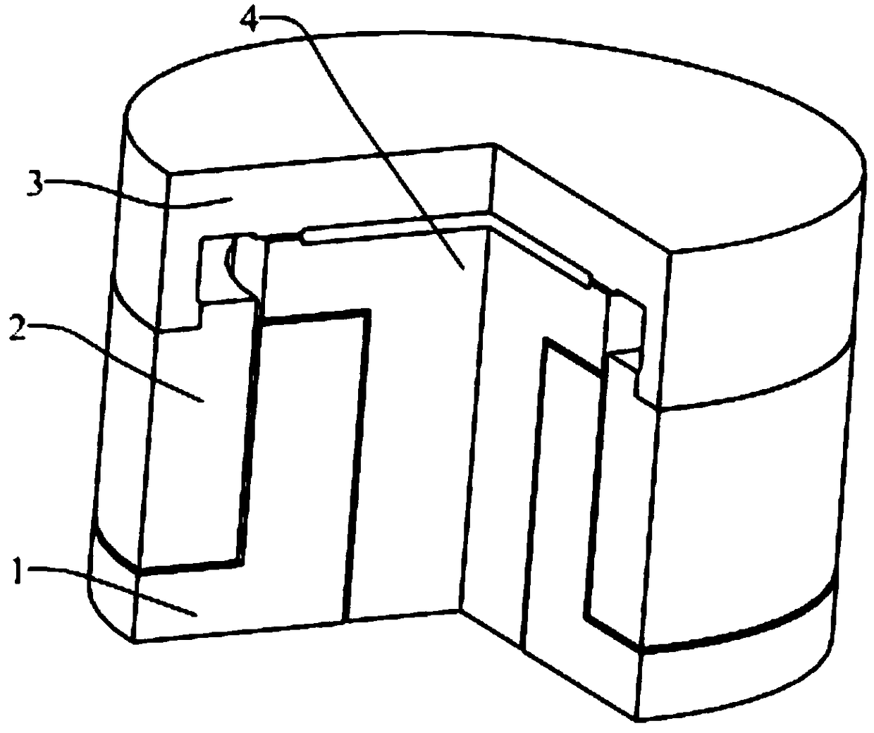
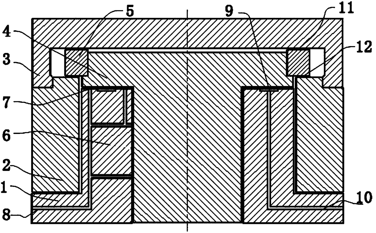
[0033] Such as Figure 1-2 As shown, an interlocking structure based on air pressure control of the present invention includes a base 1, an outer mover 2, a workbench 3, an inner mover 4 and a friction block 5, and the base 1 moves a guiding platform 6, so The outer mover 2 is cooperatingly arranged on the outside of the motion guide table 6, the inner mover 4 is inserted in the motion guide table, the workbench 3 is an annular concave structure, the workbench 3 is fixedly connected above the outer mover 2, and the workbench 3 Cover and buckle the inner mover 4 on the outer mover 2, and the friction block 5 is fixedly arranged on the inner mover 4; an air bearing surface 7 is provided on the entire contact surface between the motion guide table 6 and the inner mover 4 , the air bearing surface 7 is a relatively airtight space, the air bearing surface 7 is connected with a positive pressure air supply channel 8, and a vacuum chamber 9 is provided between the top surface of the ...
Embodiment 2
[0039] Such as Figure 1-2 As shown, the present invention is an interlocking structure based on air pressure control. On the basis of Embodiment 1, the positive pressure air supply channel 8 is arranged in the inner rotor 4 and communicates with the air bearing surface 7, and the negative pressure air supply channel The channel 10 is also arranged in the inner mover 4 and communicates with the vacuum chamber 9 , and the vacuum chamber 9 is arranged on the inner mover 4 corresponding to the top surface of the motion guide table 6 . The upper friction block 5 of the inner mover 4 and the outer mover 2 are connected through the lower friction surface 12 to realize interlocking cooperation.
[0040]An interlocking structure based on air pressure control of the present invention realizes the conversion of two moving parts into contact and non-contact states by using the opening and closing of positive and negative pressures, thereby realizing the interlocking and unlocking of the ...
Embodiment 3
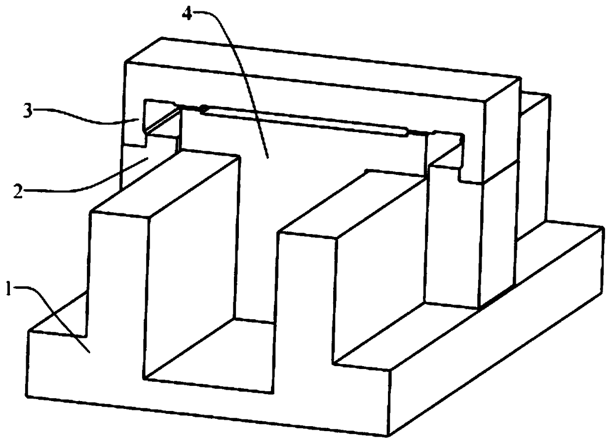
[0042] Such as Figure 3-4 As shown, an interlocking structure based on air pressure control of the present invention includes a base 1, an outer mover 2, a workbench 3, an inner mover 4 and a friction block 5, and the base 1 moves a guiding platform 6, so The outer mover 2 is cooperatingly arranged on the outside of the motion guide table 6, the inner mover 4 is a convex structure, and the inner mover 4 is inserted in the motion guide table, the workbench 3 is a concave structure, and the workbench 3 is fixedly connected to the Above the outer mover 2, the friction block 5 is fixedly arranged on the inner mover 4; an air floating surface 7 is provided between the motion guide table 6 and the inner mover 4, and the air floating surface 7 is connected with a positive pressure air supply channel 8, A vacuum chamber 9 is provided between the top surface of the motion guide table 6 and the inner mover 4 , and the vacuum chamber 9 is communicated with a negative pressure gas supply...
PUM
 Abstract
Description
Claims
Application Information
 - R&D
- Intellectual Property
- Life Sciences
- Materials
- Tech Scout
- Unparalleled Data Quality
- Higher Quality Content
- 60% Fewer Hallucinations
Browse by: Latest US Patents, China's latest patents, Technical Efficacy Thesaurus, Application Domain, Technology Topic, Popular Technical Reports.
© 2025 PatSnap. All rights reserved.Legal|Privacy policy|Modern Slavery Act Transparency Statement|Sitemap|About US| Contact US: help@patsnap.com


