Robot tool coordinate system calibration method based on planar constraints

A technology of tool coordinate system and calibration method, which is applied in the field of industrial robot tool coordinate system calibration, can solve the problems of limited calibration accuracy, low calibration efficiency, unsuitable for large-scale promotion, etc., and achieves the effect of simplifying the measurement process and high calibration efficiency.

Active Publication Date: 2018-11-02
FOSHAN INST OF INTELLIGENT EQUIP TECH +1
View PDF5 Cites 17 Cited by
  • Summary
  • Abstract
  • Description
  • Claims
  • Application Information

AI Technical Summary

Problems solved by technology

Since this method depends entirely on the operator's visual operation when calibrating TCP, the calibration accuracy is very limited, resulting in large errors in calibrating TCF, so it is not suitable for applications with high precision requirements such as laser processing.
[0004] The paper "Robot TCF Calibration Based on Planar Template" discloses a robot tool coordinate s

Method used


Image

  • Robot tool coordinate system calibration method based on planar constraints
  • Robot tool coordinate system calibration method based on planar constraints
  • Robot tool coordinate system calibration method based on planar constraints

Examples


Example Embodiment

[0024] In the following, the concept, specific structure and technical effects of the present invention will be clearly and completely described in conjunction with the embodiments and the drawings to fully understand the purpose, features and effects of the present invention. Obviously, the described embodiments are only a part of the embodiments of the present invention, rather than all of them. Based on the embodiments of the present invention, other embodiments obtained by those skilled in the art without creative work belong to The scope of protection of the present invention. In addition, all the connection / connection relationships mentioned in the text do not only refer to the direct connection of the components, but refer to the fact that a better connection structure can be formed by adding or reducing connection accessories according to specific implementation conditions. The various technical features in the invention can be combined interactively on the premise of n...


PUM


Abstract

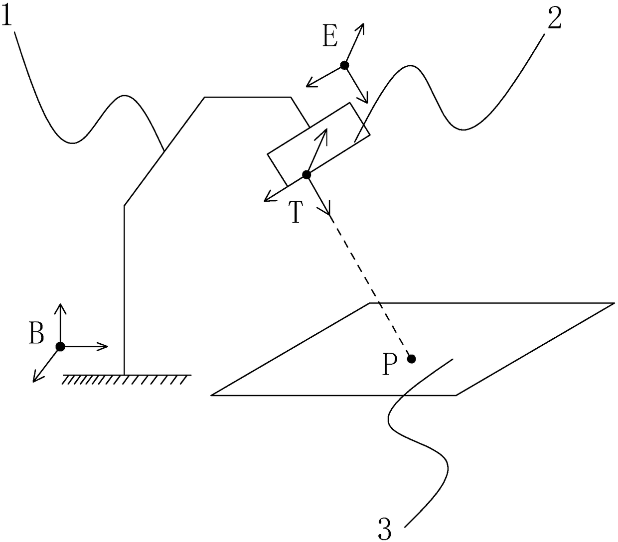
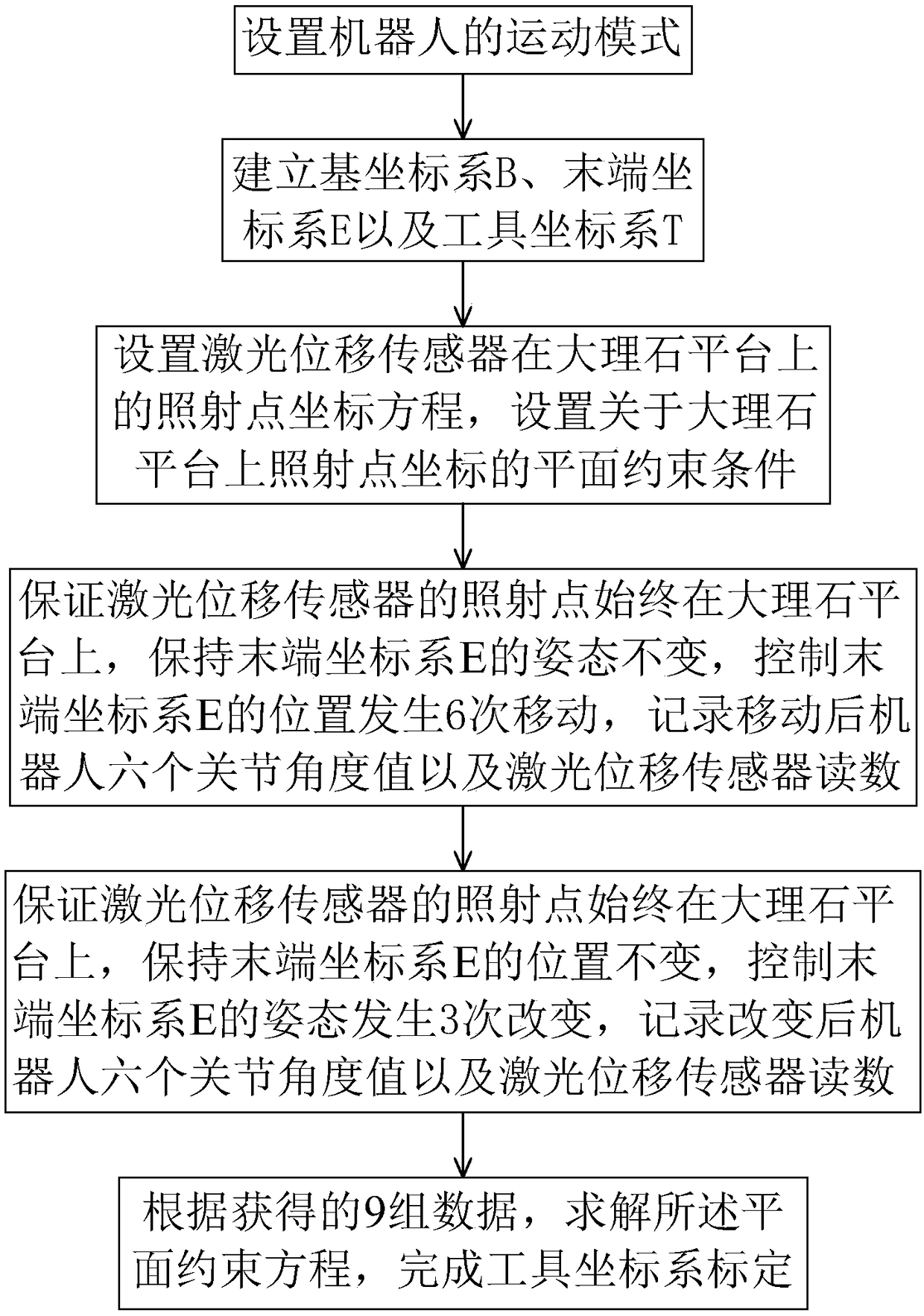
The invention discloses a robot tool coordinate system calibration method based on planar constraints. The robot tool coordinate system calibration method comprises the steps of: setting a motion modeof a robot; establishing a base coordinate system B, an end coordinate system E and a tool coordinate system T; establishing a planar constraint condition; ensuring that an irradiation point is always on a marble platform, keeping the attitude of the end coordinate system E unchanged, and controlling the position of the end coordinate system E to change for six times; ensuring that the irradiation point is always on a marble platform, keeping the position of the end coordinate system E unchanged, and controlling the attitude of the end coordinate system E to change for three times; and solving an irradiation point coordinate equation. During the tool coordinate system calibration process, the calibration of the tool coordinate system can be completed by solving the irradiation point coordinate equation of a laser displacement sensor, the solving of the irradiation point coordinate equation only needs to complete the measurement of 9 sets of data, the calibration efficiency is high, and the laser displacement sensor is utilized for distance detection to ensure sufficient calibration precision of the tool coordinate system.

Description

technical field [0001] The invention belongs to the field of tool coordinate system calibration of industrial robots, and aims at the tool coordinate system calibration of an industrial 6-axis robot with a laser displacement sensor clamped at the end, and more specifically relates to a tool coordinate system calibration method of an industrial robot based on plane constraints. Background technique [0002] The calibration system of the tool coordinate system is generally divided into two parts of calibration, that is, the position calibration of the tool center point and the attitude calibration of the tool coordinate system. In industrial production lines, special parts are usually fixed on the end effector of industrial robots as tools, such as fixtures, welding guns and other devices. A coordinate system is usually established at a fixed position on these tools, the so-called tool coordinate system . The trajectory planning of the robot is usually planned for a certain p...

Claims


Application Information

Patent Timeline
IPC IPC(8): G01B11/00
CPCG01B11/002
Inventor 王坤周星朱志红
Owner FOSHAN INST OF INTELLIGENT EQUIP TECH
Why Eureka
Try Eureka