Test system and method for joint destruction effect of laser and surface airflow

A test system and airflow technology, applied in the field of laser applications, can solve the problems of narrow application range, large volume, high cost of the test system, etc., and achieve the effect of wide application range, small size and simple structure

Inactive Publication Date: 2018-11-02
NORTHWEST INST OF NUCLEAR TECH
View PDF4 Cites 3 Cited by
  • Summary
  • Abstract
  • Description
  • Claims
  • Application Information

AI Technical Summary

Problems solved by technology

[0003] The purpose of the present invention is to overcome the disadvantages of high cost, large volume and narrow application range of the existing test system, and propose a laser irradiation effect test system and method that uses high-speed rotation to simulate the flight state of the target

Method used


Image

  • Test system and method for joint destruction effect of laser and surface airflow
  • Test system and method for joint destruction effect of laser and surface airflow
  • Test system and method for joint destruction effect of laser and surface airflow

Examples


Embodiment 1

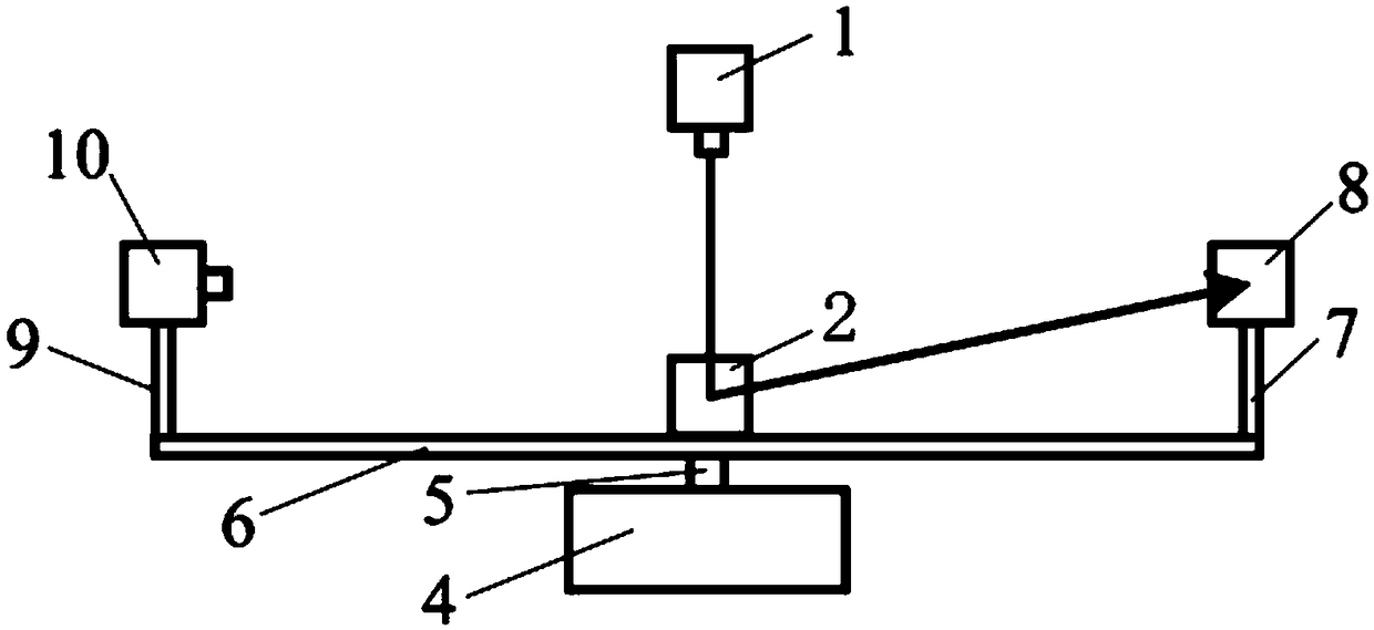
[0033] see figure 1 and image 3 , a test system for the combined destructive effect of laser and surface airflow, including a target 8, a beam module, an airflow simulation module and a monitoring device 10, the beam module includes a laser 1 and a first total reflection mirror 2, and the first total reflection mirror 2 is set on the exit optical path of the laser 1; the airflow simulation module includes a rotating support assembly, the rotation support assembly includes a motor 4 and a support assembly, and the motor shaft 5 is fixedly connected to the middle of the support assembly; the optical axis of the laser 1 exits through the Through the center of the first total reflection mirror 2 and the axis of the motor rotating shaft 5.

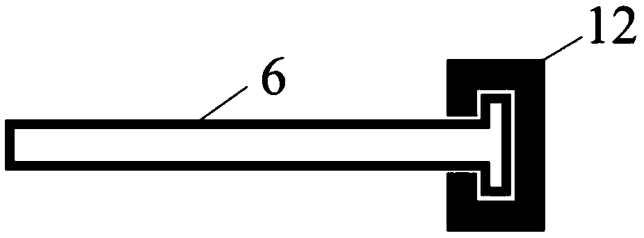
[0034] The support assembly includes a rotating rod 6 and a target support rod 7 and a monitoring equipment support rod 9 vertically installed at the two ends of the rotating rod 6. The first full reflection mirror 2 is fixed on the middle pa...

Embodiment 2

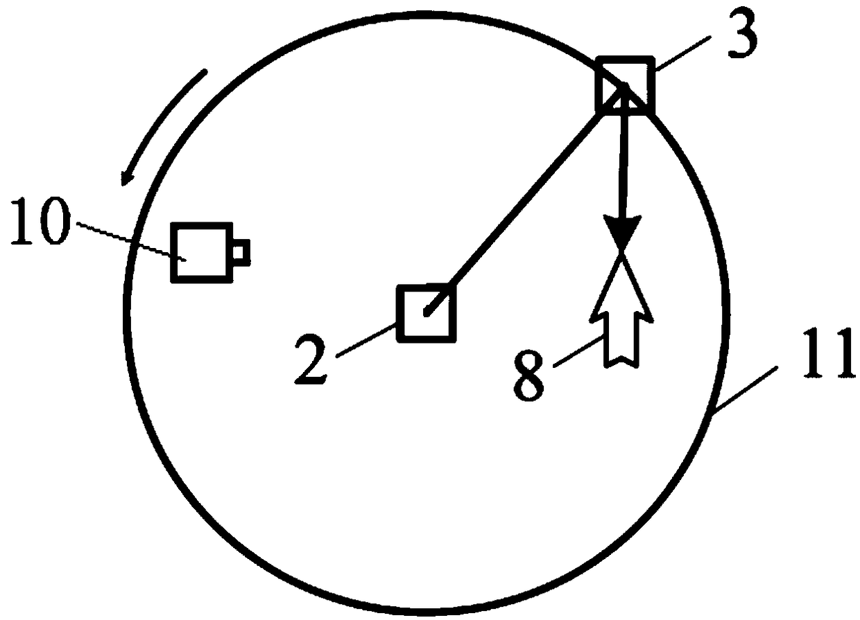
[0044] see figure 2 , a test system for the combined destructive effect of laser and surface airflow, including a target 8, a beam module, an airflow simulation module and a monitoring device 10, the beam module includes a laser 1 and a first total reflection mirror 2, and the first total reflection mirror 2 is set on the exit optical path of the laser 1; the airflow simulation module includes a rotating support assembly, the rotation support assembly includes a motor 4 and a support assembly, and the motor shaft 5 is fixedly connected to the middle of the support assembly; the optical axis of the laser 1 exits through the Through the center of the first total reflection mirror 2 and the axis of the motor rotating shaft 5.

[0045] The support assembly includes a turntable 11 and a target pole 7 and a monitoring equipment pole 9 installed on the outer edge of the turntable 11, the first total reflection mirror 2 is fixed at the center of the turntable 11, and the target 8 is ...


PUM


Abstract

The invention belongs to the laser application technology field, relates to a test system and method for the joint destruction effect of laser and the surface airflow and aims to solve disadvantages of high cost, the huge size and the narrow application scope existing in a test system in the prior art. The test system for the joint destruction effect of the laser and the surface airflow comprisesa target, a beam module, an airflow simulation module and a monitoring device, wherein the beam module comprises a laser device and a first total reflective mirror, the first total reflective mirror is arranged on an emission light path of the laser device, the airflow simulation module comprises a motor and a supporting assembly fixedly connected with a motor rotation shaft, the first total reflective mirror, the target and the monitoring device are fixed at an upper end of the supporting assembly, the first total reflective mirror is arranged in the middle, the target and the monitoring device are arranged at two sides of the first total reflective mirror, the light emitted by the laser device is reflected by the first total reflective mirror to irradiate onto the target, and a light signal on the surface of the target enters the monitoring device and is not blocked by the first total reflective mirror.

Description

technical field [0001] The invention belongs to the technical field of laser applications, and relates to a test system and method for the combined destruction effect of laser and surface airflow, in particular to a laser irradiation effect test system and method for simulating the flight state of a target by means of high-speed rotation. Background technique [0002] In the study of the effect of high-power laser damage to flying targets, it is necessary to simulate the flight state of the target in a laboratory environment. The usual practice is to use a wind tunnel to conduct simulation experiments to study the influence of surface airflow on the laser damage effect of the target. In the Chinese patent with the publication number CN105973563A "A Test System and Method for Combined Destruction Effect of Intense Laser and Supersonic Wind Tunnel", a method for studying the effect of laser irradiation by using a wind tunnel to simulate the airflow on the surface of the target...

Claims


Application Information

Patent Timeline
IPC IPC(8): G01M9/04
CPCG01M9/04
Inventor 吴涛涛陈绍武朱永祥韦成华宋明英吕玉伟王立君
Owner NORTHWEST INST OF NUCLEAR TECH
Why Eureka
Try Eureka