
Rigid body sliding wire with good heat dissipation performance

A technology with heat dissipation performance and rigid body, applied in conductors, non-insulated conductors, metal/alloy conductors and other directions, it can solve the problems of easy damage to the sliding wire, many metals, and sagging of the sliding wire system, so as to reduce labor intensity, enhance heat dissipation effect, Good heat dissipation effect

Inactive Publication Date: 2018-11-02
扬州联胜电气有限公司
View PDF0 Cites 2 Cited by
  • Summary
  • Abstract
  • Description
  • Claims
  • Application Information

AI Technical Summary

Problems solved by technology

However, when the transmission trolley line exceeding 2000A is constructed by the above method, the existing structure is difficult to ensure the heat dissipation effect. For the rigid body trolley copper rod through which a large current passes, the rigid body trolley copper rod needs to have a larger cross-sectional area, and the large current When passing through the rigid body slide wire, due to the small surface area of ​​the rigid body slide wire copper rod, the large current passes through the rigid body slide wire copper rod to dissipate heat slowly, so the temperature of the rigid body slide wire copper rod rises, resulting in an increase in the resistance of the rigid body slide wire copper rod , the energy consumption increases, and the copper rod of the rigid sliding wire uses more metal, and the cost is relatively high
The sliding wires used in high temperature, open air, rain, snow, dust and other harsh occasions are rigid sliding wires with unstable structure. During operation, the sliding wire system sags and shakes greatly, which makes it difficult to get power from the equipment and the sliding wires are easy to be damaged.

Method used


Image

  • Rigid body sliding wire with good heat dissipation performance

Examples


Embodiment Construction

[0013] A rigid sliding wire with good heat dissipation performance of the present invention will be described in detail below in conjunction with the accompanying drawings.

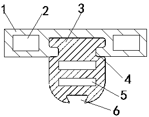
[0014] like figure 1 As shown, a rigid body sliding wire with good heat dissipation performance includes a base material 1 with an annular mounting groove in the middle and a copper rod 3 installed in the annular mounting groove of the base material 1; the annular mounting groove of the base material 1 has two A rectangular first heat dissipation hole 2 is provided on each side, and the base material 1 is made of aluminum material; the end of the copper rod 3 is provided with an annular groove 4, and the front end of the copper rod 3 is provided with a dovetail groove 6, and the copper rod 3 There are two second heat dissipation holes 5 distributed in parallel in the middle, and the copper rod 3 is made of copper material; the first heat dissipation hole 2 is provided with a heat-conducting material with ...


PUM


Abstract

The invention provides a rigid body sliding wire with good heat dissipation performance. The rigid body sliding wire comprises a base material and a copper rod, wherein an annular mounting groove is formed in the middle part of the base material; the copper rod is mounted inside the annular mounting groove of the base material; an oblong first heat dissipation hole is formed in two sides of the annular mounting groove of the base material respectively, and the base material is made of aluminum; an annular groove is formed in the tail end of the copper rod, a dovetail groove is formed in the front end of the copper rod, two second heat dissipation holes distributed in parallel are formed in the middle position of the copper rod, and the copper rod is made of copper. According to the rigid body sliding wire provided by the invention, the upper part of the copper rod is of an H-shaped structure, the lower part of the copper rod is of a dovetail groove structure, the surface area per unitlength is increased, the middle part of the copper rod is provided with a heat conducting material, the heat dissipation effect is strengthened, the carrying capacity is improved, the weight per unitlength is reduced, and the labor intensity of worker field installation is alleviated; and the copper rod is mounted at the bottom of the aluminum base material, so that the rigidity of the rigid bodysliding wire is improved.

Description

technical field [0001] The invention relates to a rigid sliding wire, in particular to a rigid sliding wire with good heat dissipation performance. Background technique [0002] At present, the copper rod of the rigid sliding wire is generally in the shape of a dovetail groove or an I-shaped steel. However, when the transmission trolley line exceeding 2000A is constructed by the above method, the existing structure is difficult to ensure the heat dissipation effect. For the rigid body trolley copper rod through which a large current passes, it is required that the rigid body trolley copper rod have a larger cross-sectional area, and the large current When passing through the rigid body sliding wire, due to the small surface area of ​​the rigid body sliding wire copper rod, the heat dissipation of large current through the rigid body sliding wire copper rod is slow, so the temperature of the rigid body sliding wire copper rod rises, resulting in an increase in the resistance ...

Claims


Application Information

Patent Timeline
IPC IPC(8): H01B9/00H01B5/00H01B5/02H01B1/02
CPCH01B9/006H01B1/02H01B5/002H01B5/02
Inventor 尹昌圣
Owner 扬州联胜电气有限公司
Learn More