Antenna device and electronic device

An antenna device and electronic equipment technology, which is applied to antenna supports/installation devices, antennas, and devices that enable antennas to work in different frequency bands at the same time, can solve the problems of reduced antenna performance, complex structure of MIMO antennas, and large occupancy. Ensure antenna performance, meet ultra-thin design requirements, and reduce occupancy

Active Publication Date: 2018-11-02
HUAWEI TECH CO LTD
View PDF5 Cites 7 Cited by
  • Summary
  • Abstract
  • Description
  • Claims
  • Application Information

AI Technical Summary

Problems solved by technology

Although such a design idea can achieve good isolation to a certain extent, the resulting MIMO antenna structure is generally more complex and takes up a large space, and the introduction of decoupling methods often reduces the performance of the antenna itself to a certain extent.

Method used


Image

  • Antenna device and electronic device
  • Antenna device and electronic device
  • Antenna device and electronic device

Examples


Embodiment Construction

[0031] The technical solution in this application will be described below with reference to the accompanying drawings.

[0032] Embodiments of the present invention relate to electronic equipment. The electronic device indicates an intelligent electronic device with a wireless communication function. For example, the electronic device is, for example, a smart phone, a tablet computer or other mobile user terminal devices.

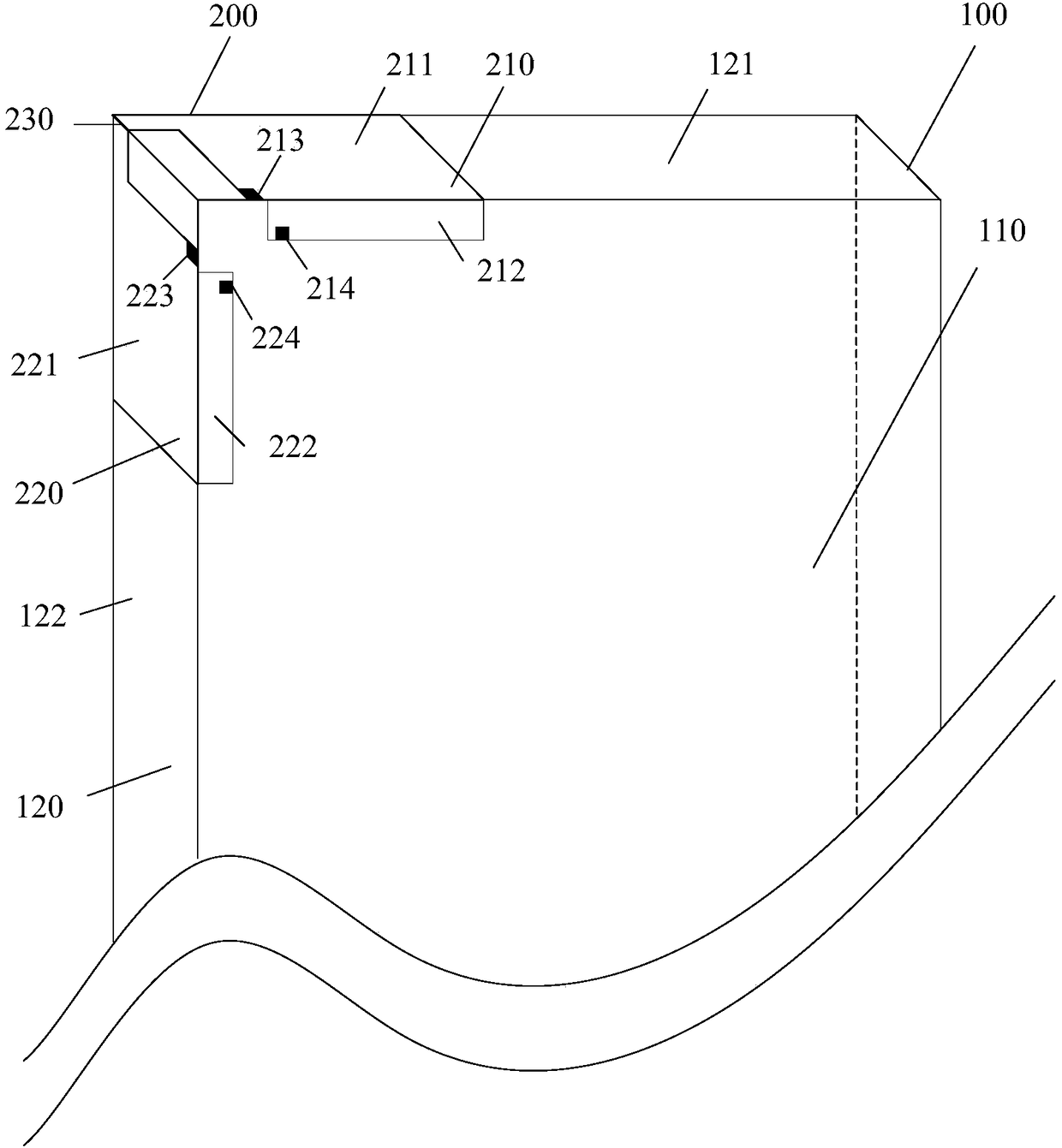
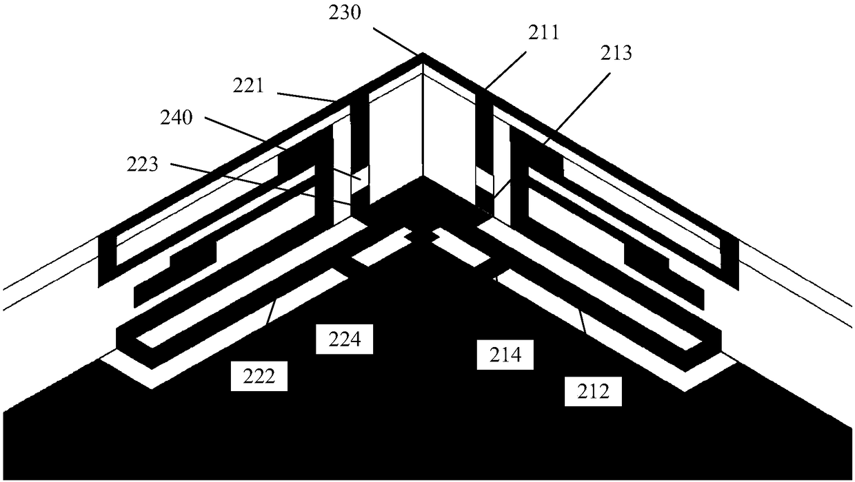
[0033] figure 1 It is a schematic diagram of the antenna device 200 in the electronic device 100 provided by the embodiment of the present invention. The electronic device 100 includes a metal ground plane 110 and a side frame 120 surrounding the metal ground plane 110 , the side frame 120 is perpendicular to the metal ground plane 110 , and the side frame 120 includes a first side 121 and a second side 122 perpendicular to each other. Such as figure 1 As shown, the antenna device 200 includes:

[0034] The first antenna radiator 210 includes a first a...


PUM


Abstract

The present application provides an antenna device and an electronic device. The antenna device comprises a first antenna radiator and a second antenna radiator, wherein the first antenna radiator comprises a first antenna side radiator on a first side of the electronic device and a first antenna bottom edge radiator located on a metal ground plane of the electronic device; the first antenna sideradiator comprises a first feed port; the first antenna bottom edge radiator comprises a second feed port; the two feed ports have different operating frequencies; the second antenna radiator comprises a second antenna side radiator located on a second side of the electronic device and a second antenna bottom edge radiator located on the metal ground plane; the second antenna side radiator comprises a third feed port; the second antenna bottom edge radiator comprises a fourth feed port; and the two feed ports have different working frequencies; the two side radiators are connected through a metal wire at the junction of the first side and the second side; the two bottom edge radiators are separated from each other and perpendicular to each other, so that a compact layout of the antenna canbe realized; also, the isolation degree between the antennas can be ensured.

Description

technical field [0001] The present application relates to the field of antennas, and more particularly, to an antenna device and electronic equipment. Background technique [0002] Multiple-Input Multiple-Output (MIMO) antenna technology is one of the main core technologies of MIMO wireless communication technology. The traditional Single-Input Single-Output (SISO) antenna system has a large channel capacity. It has an unbreakable bottleneck - the limitation of Shannon's capacity. However, under the condition of no size limitation, the more the number of antennas, the system throughput will increase exponentially with the number of antennas. With the maturity of 4G communication, 4.5G and 5G are being extensively studied. There is no doubt that the channel capacity indicator will become one of the core concerns of 5G communications. The MIMO technology based on multiple antennas can provide greater channel capacity without expanding the frequency band, and the channel cap...

Claims


Application Information

Patent Timeline
Patent Type & Authority Applications(China)
IPC IPC(8): H01Q1/38H01Q1/50H01Q1/52H01Q1/22
CPCH01Q1/22H01Q1/38H01Q1/50H01Q1/521H01Q5/20H01Q5/50
Inventor 施学良温怀林王俊
Owner HUAWEI TECH CO LTD
Why Eureka
Try Eureka