T1 parameter diagram imaging method and magnetic resonance imaging system
A technology of magnetic resonance imaging and imaging method, applied in the medical field, can solve problems such as small space coverage, and achieve the effects of expanding space coverage, saving scanning time, and improving scanning efficiency
- Summary
- Abstract
- Description
- Claims
- Application Information
AI Technical Summary
Problems solved by technology
Method used
Image
Examples
Embodiment 1
[0057] The embodiment of the present invention provides a T1 parameter map imaging method. The T1 parameter map imaging method can be used to obtain a whole-heart T1 parameter map of the heart.
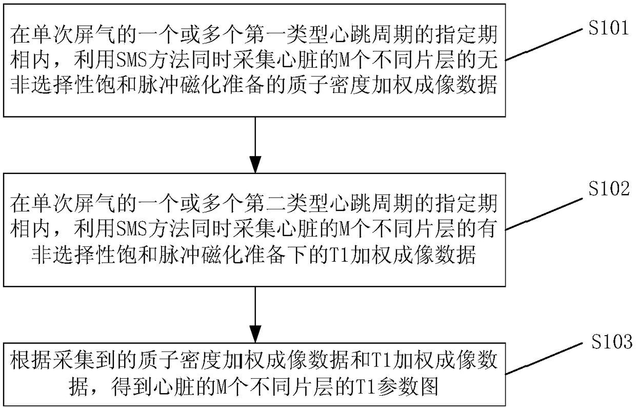
[0058] figure 1 This is an example flow chart of a T1 parameter map imaging method provided by an embodiment of the present invention. Such as figure 1 As shown, in this embodiment, the T1 parameter map imaging method may include the following steps:
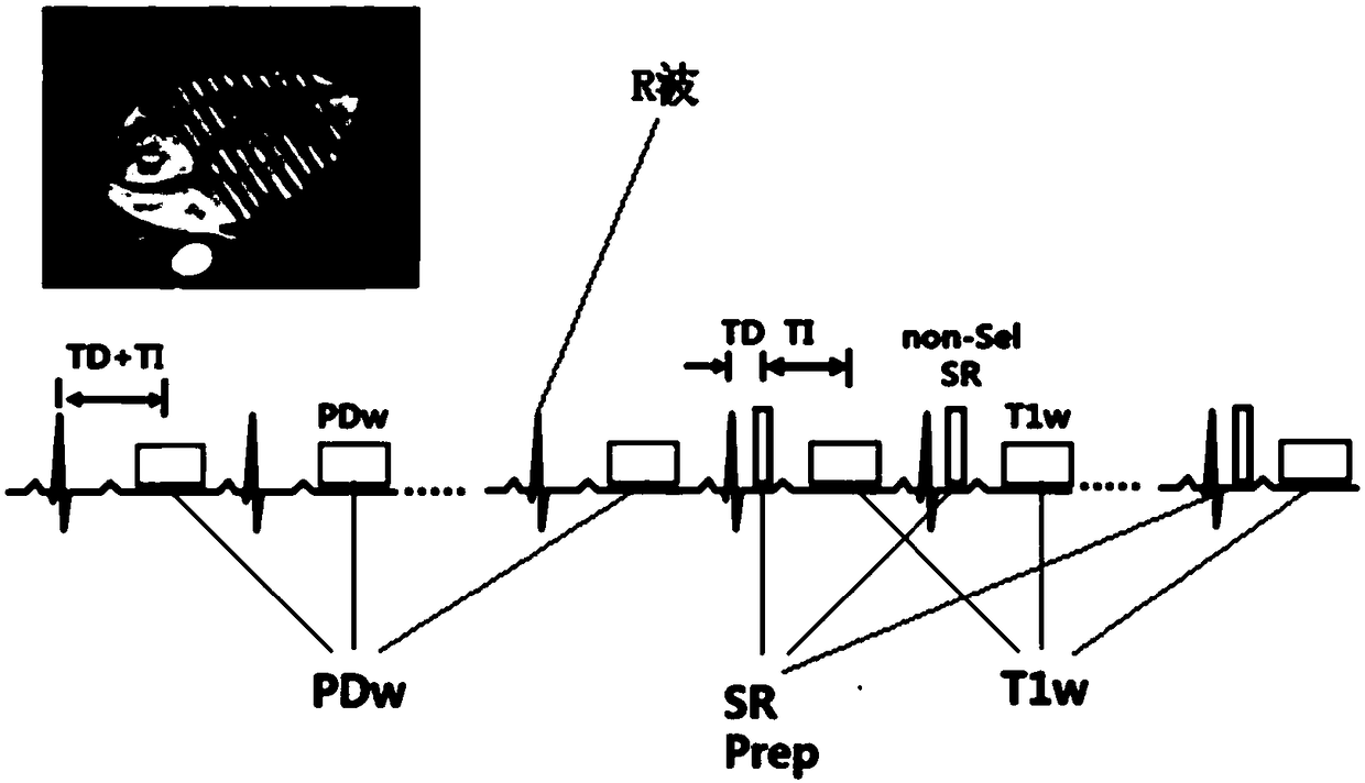
[0059] S101, using SMS (Simultaneously Multi Slice, simultaneous multi-layer simultaneous excitation) method to simultaneously collect non-selective saturation of M different slices of the heart in one or more specified phases of the first type heartbeat cycle in a single breath-hold Proton density weighted imaging data prepared by pulse magnetization.
[0060] Optionally, the period of a single breath-hold may correspond to one or more first-type heartbeat cycles, and each first-type heartbeat period corresponds to a different period of a si...
Embodiment 2
[0101] An embodiment of the present invention provides a T1 parameter map imaging system. The system includes a processor and a memory. The memory is used to store instructions. When the instructions are executed by the processor, the system realizes any T1 parameter in the first embodiment. Figure imaging method.
Embodiment 3
[0103] The embodiment of the present invention provides a magnetic resonance imaging system.
[0104] Figure 5 It is a block diagram of a magnetic resonance imaging (MRI) system according to some embodiments of the present application. As explained, the MRI system 100 may include an MRI scanner 110, a controller 120, a processor 130, and a display 140. The MRI scanner 110 may include a magnet module 111 and a radio frequency (RF) module 112. In some embodiments, the MRI scanner 110 may perform scanning on a subject. In some embodiments, the scan may be an imaging scan used to generate magnetic resonance (MR) images, or a pre-scan used to calibrate the MRI system 100. The magnet module 111 may include a main magnetic field generator and / or a gradient magnetic field generator ( Figure 5 Not shown in). The main magnetic field generator can generate a static magnetic field B0 during scanning. The main magnetic field generator can be of various types, including, for example, per...
PUM
 Abstract
Description
Claims
Application Information
 - R&D
- Intellectual Property
- Life Sciences
- Materials
- Tech Scout
- Unparalleled Data Quality
- Higher Quality Content
- 60% Fewer Hallucinations
Browse by: Latest US Patents, China's latest patents, Technical Efficacy Thesaurus, Application Domain, Technology Topic, Popular Technical Reports.
© 2025 PatSnap. All rights reserved.Legal|Privacy policy|Modern Slavery Act Transparency Statement|Sitemap|About US| Contact US: help@patsnap.com


