Intelligent glue gun

A glue gun, intelligent technology, applied in the direction of coating, coating liquid on the surface, etc., can solve the problems of affecting efficiency, waste of colloid materials, difficulty in finding a suitable gear, etc., and achieve the effect of uniform glue output

Inactive Publication Date: 2018-11-06
贵州建工集团第七建筑工程有限责任公司
View PDF0 Cites 4 Cited by
  • Summary
  • Abstract
  • Description
  • Claims
  • Application Information

AI Technical Summary

Problems solved by technology

[0005] 1. The propelling force is realized by hand holding back and forth, which is labor intensive and not conducive to long-term work. Moreover, when injecting glue, the hand moves backwards, causing the glue gun to shake, which is not conducive to injection molding;
[0006] 2. When a step is paused, the residual extrusion force in the glue tank makes the glue continue to be extruded, resulting in waste of glue materials, and the nozzle needs to be cleaned before continuing to use, which affects the efficiency;
[0007] 3. In addition to the horizontal movement, the hand also needs to act as a propulsion function, so it is impossible to focus all the attention on the quality of the glue, and the operation is inconvenient
[0009] 1. The horizontal movement speed of the hand must be used to adapt to the glue output speed of the electric feed, which is not easy to grasp accurately, which affects the forming quality, and the construction workers are also prone to fatigue;
[0010] 2. Most of them adopt stepped speed regulation, and it is difficult to find a suitable gear for some construction positions;
[0011] 3. When the switch position of the glue gun is suspended, the residual pressure in the glue tank makes the glue continue to be squeezed out, which affects the quality of glue injection and causes waste of glue resources;

Method used


Image

  • Intelligent glue gun
  • Intelligent glue gun
  • Intelligent glue gun

Examples


Embodiment Construction

[0022] The specific implementation, features and functions of a smart glue gun device according to the present invention will be described in detail below with reference to the accompanying drawings and preferred embodiments.

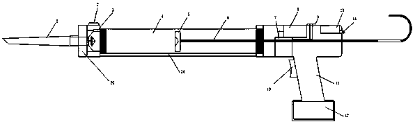
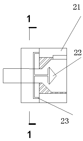
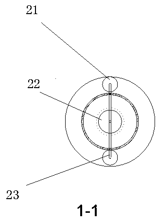
[0023] Such as Figure 1-3 As shown, a kind of intelligent glue gun of the present invention comprises gun mouth 1, infrared velocity detector 2, gun body 4, glue port opening controller 20, screw rod 6, switch 10, glue tank 24, wherein: gun mouth 1 is installed on The front end of the gun body 4, the glue tank 24 is installed in the middle of the gun body 4, the glue tank 24 is connected with the gun mouth 1 through the glue mouth opening controller 20, the gun handle 11 is installed at the rear lower part of the gun body 4, and the switch 10 is arranged on the gun handle 11 The front end of the gun body 4 is provided with an infrared speedometer 2, the pressure sensor 3 is located at the front end of the glue tank 24, the screw rod 6 passes through th...


PUM


Abstract

The invention discloses an intelligent glue gun. A gun nozzle (1) is installed at the front end of a gun body (4); a glue tank (24) is installed on the middle portion of the gun body (4); the glue tank (24) and the gun nozzle (1) are connected through a glue port opening controller (20); a gun handle (11) is installed on the rear lower portion of the gun body (4); a switch (10) is arranged on thegun handle (11); an infrared speed measuring device (2) is arranged at the front end of the gun body (4); a pressure sensor (3) is arranged at the front end of the glue tank (24); a screw (6) penetrates through a screw transmission (7) located on the rear portion of the gun body (4), the front end is connected with a gun bowl (5) located in the glue tank (24), and the rear end is located outside the gun body (4); a propelling speed adjusting motor (8) and a transmission clutch (9) are installed on the screw transmission (7); a single-chip microcomputer processor (13) is installed at the tail end of the gun body (4); and a propelling speed relevance adjustor (14) is installed on the single-chip microcomputer processor (13). The intelligent glue gun can adjust the glue discharging speed in aself-adaptive manner, glue discharging is stable, the gluing efficiency can be improved, the labor intensity of personnel is relieved, and materials are saved.

Description

technical field [0001] The invention belongs to the field of construction machinery, and in particular relates to an intelligent glue gun. Background technique [0002] In modern building curtain wall engineering and interior decoration engineering, weather-resistant adhesives, glass adhesives and seam adhesives are widely used. The construction of such adhesives requires the use of extrusion coating devices. [0003] Existing colloid extrusion devices can be generally divided into two categories, one is a manual mechanical feed glue gun, and the other is an electric feed glue gun. [0004] Manual mechanical feed glue guns have the following drawbacks: [0005] 1. The propelling force is achieved by holding the hand back and forth, which is labor-intensive and not conducive to long-term work. Moreover, when injecting glue, the hand moves backwards, causing the glue gun to shake, which is not conducive to injection molding; [0006] 2. When a step is paused, the residual ...

Claims


Application Information

Patent Timeline
Patent Type & Authority Applications(China)
IPC IPC(8): B05C17/01
CPCB05C17/0103B05C17/0133B05C17/014
Inventor 周炳秋陈宇潘吉应任鹤鸣韩用代云峰张乾义李明凤陶旭刘云
Owner 贵州建工集团第七建筑工程有限责任公司
Why Eureka
Try Eureka