
Concrete gravel separation and recovery device

A technology for sand and gravel separation and recycling equipment, which is applied in solid separation, wet separation, filtration and screening, etc. It can solve the problems of waste of resources, single function, and high noise, and achieve the goals of preventing equipment resonance, good filtering effect, and reducing waste Effect

Inactive Publication Date: 2018-11-06
广州臻太机械制造有限公司
View PDF4 Cites 12 Cited by
  • Summary
  • Abstract
  • Description
  • Claims
  • Application Information

AI Technical Summary

Problems solved by technology

[0002] A large amount of waste water and waste residues are produced during the production of ready-mixed concrete. These waste water and waste residues are usually discharged directly without treatment, causing great pollution to the environment. The existing concrete cleaning and separation equipment has limited separation effect on solids and liquids, and it is difficult to completely separate them Sand and stone, not only cannot complete the recycling of sand and stone, but also cannot realize the recycling of slurry water, sand and stone, which wastes resources and pollutes the environment. Disposal of redundant concrete and exhausted concrete that cannot be used due to quality problems, etc.
[0003] At present, most of the existing concrete sand and gravel separation and recovery equipment have single functions, and can only perform preliminary separation of sand and gravel, and the separation effect is poor. At the same time, the sand cannot be further subdivided, which is not conducive to efficient recycling. The recovery equipment is equipped with shock-absorbing components, so the vibration generated during the separation of sand and gravel is likely to have a negative impact on the life of the entire device. Finally, the existing sand and gravel separation and recovery equipment is noisy, the working environment is poor, and it is not beautiful enough.

Method used


Image

  • Concrete gravel separation and recovery device
  • Concrete gravel separation and recovery device
  • Concrete gravel separation and recovery device

Examples


Embodiment Construction

[0027] The following will clearly and completely describe the technical solutions in the embodiments of the present invention with reference to the accompanying drawings in the embodiments of the present invention. Obviously, the described embodiments are only some, not all, embodiments of the present invention. Based on the embodiments of the present invention, all other embodiments obtained by persons of ordinary skill in the art without making creative efforts belong to the protection scope of the present invention.

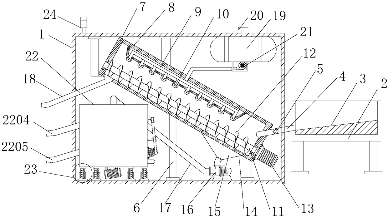
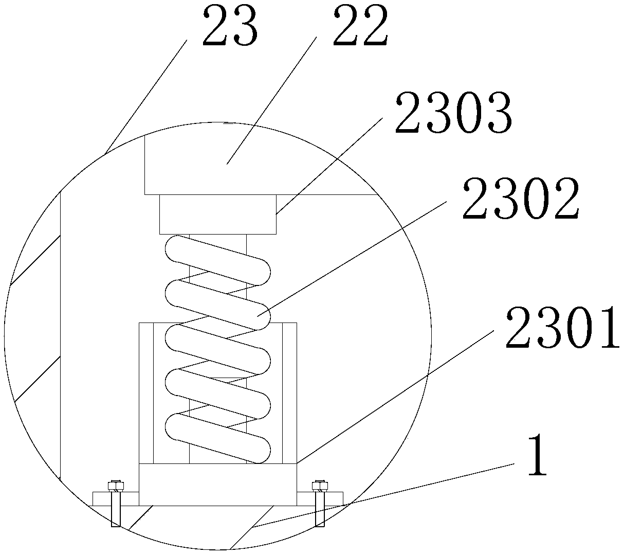
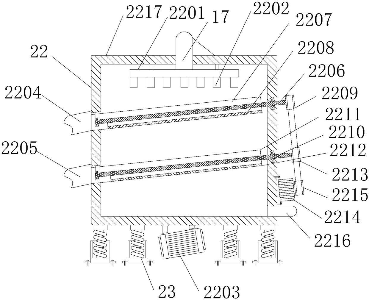
[0028] see Figure 1~4 , in an embodiment of the present invention, a concrete sand and gravel separation and recovery equipment, including a main box 1, a sand and gravel separation module, a feed box 2, a sand material screening module 22 and a shock absorption module 23, the main box 1 The upper end is provided with a warning light, and the left side of the inner bottom of the main box 1 is provided with a shock absorbing module 23. The frame 6 is connecte...


PUM


Abstract

The invention discloses a concrete gravel separation and recovery device. The device comprises a main box body, a gravel separation module, a feeding box, a gravel screening module and damping modules. According to the device, the structure is reasonable in design, and the practicability is high; during work, spraying heads spray water on raw materials, spraying is uniform, and the cleaning effectis better; a second motor drives a first belt wheel and a second belt wheel to rotate through a driving belt wheel so as to drive a second rotating shaft, a first V-shaped screening plate, a third rotating shaft and a second V-shaped screening plate to rotate left and right within a short distance, meanwhile, gravel can be effectively filtered and classified under the action of a vibration motor,the filtration effect is good, and the filter screen is not prone to blockage; and under the action of a coarse-hole filter screen and a fine-hole filter screen, the gravel can be effectively collected in a classified mode, the gravel can be recycled, and waste is reduced; and device resonance is prevented under the action of the damping modules, so that the influence of the vibration motor on the whole device is reduced, the main box body can also effectively isolate noise, and meanwhile, the device is elegant and attractive.

Description

technical field [0001] The invention relates to the technical field of building construction environmental protection equipment, in particular to concrete sand and gravel separation and recovery equipment. Background technique [0002] A large amount of waste water and waste residues are produced during the production of ready-mixed concrete. These waste water and waste residues are usually discharged directly without treatment, causing great pollution to the environment. The existing concrete cleaning and separation equipment has limited separation effect on solids and liquids, and it is difficult to completely separate them Sand and stone, not only cannot complete the recycling of sand and stone, but also cannot realize the recycling of slurry water, sand and stone, which wastes resources and pollutes the environment. Disposal of excess concrete and exhausted concrete that cannot be used due to quality problems. [0003] At present, most of the existing concrete sand and ...

Claims


Application Information

Patent Timeline
Patent Type & Authority Applications(China)
IPC IPC(8): B07B1/28B07B1/42B08B3/02B03B5/52
CPCB03B5/52B07B1/28B07B1/42B08B3/022
Inventor 罗晓峰
Owner 广州臻太机械制造有限公司
Learn More