Chemical equipment cleaning device

A technology for cleaning devices and chemical equipment, applied to cleaning hollow objects, cleaning methods and utensils, chemical instruments and methods, etc., can solve problems such as inability to do all-round cleaning, complicated operation, and waste of electric energy, so as to avoid waste of electric power resources , saving water resources, all-round cleaning effect

Inactive Publication Date: 2018-11-06
陈海荣
View PDF5 Cites 6 Cited by
  • Summary
  • Abstract
  • Description
  • Claims
  • Application Information

AI Technical Summary

Problems solved by technology

[0003] The existing chemical tank cleaning device is usually equipped with a water pump for pumping and spraying, and then wiping after spraying, which not only wastes electric energy, but also cannot achieve all-round cleaning. The efficiency is not high, and the operation is complicated. Therefore, it is urgently needed. A new device to solve the above problems

Method used


Image

  • Chemical equipment cleaning device
  • Chemical equipment cleaning device
  • Chemical equipment cleaning device

Examples


Embodiment 1

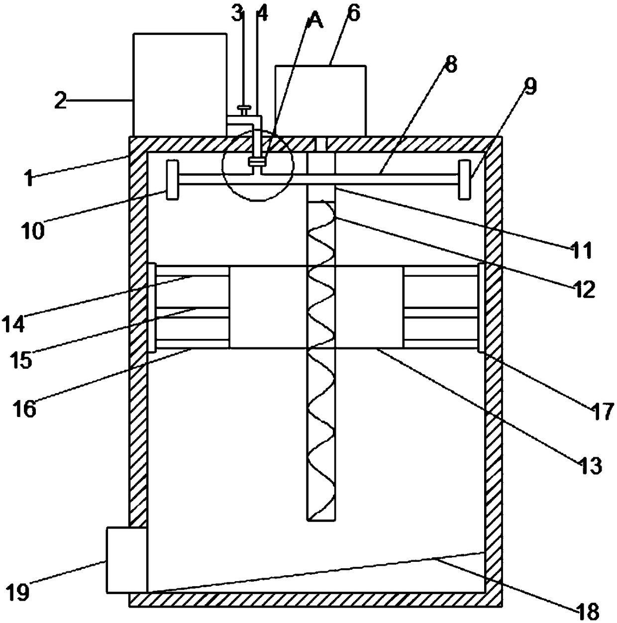
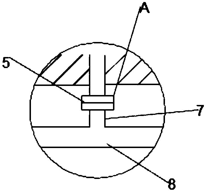
[0023] see Figure 1~2 , in an embodiment of the present invention, a chemical equipment cleaning device includes a main body 1, a water tank 2 is provided on the left side of the top outer surface of the main body 1, the water tank 2 is used to store water, and the bottom of the right wall of the water tank 2 It communicates with the left end of the first water pipe 4, the first water pipe 4 is "L" shaped, the right end of the transverse part of the first water pipe 4 is provided with a valve 3 on the outside of the water tank 2, the longitudinal direction of the first water pipe 4 The top part of the main body 1 is connected to the rotary connector 5, and the bottom of the rotary connector 5 is connected to the upper end of the second water pipe 7. The second water pipe 7 is arranged on the horizontal water pipe 8 and connected to the horizontal water pipe 8. Through, the middle outer surface of the horizontal water pipe 8 is fixedly connected with the middle outer surface o...

Embodiment 2

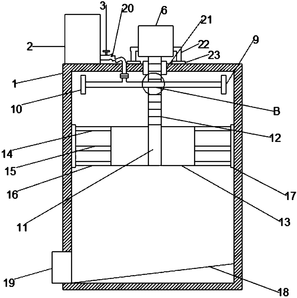
[0025] see Figure 3-4 The difference between embodiment 2 and embodiment 1 is that the first water pipe 4 is replaced by a hose 20, the length of the hose 20 can satisfy the motor 6 to move up and down, and the lower ends of the left and right sides of the motor 6 are symmetrically provided with L Rod 22, the lower end of the L rod 22 is fixedly connected with a limit block 23, and the limit block 23 is made of elastic material, which plays the role of buffering and protecting the motor 6, and the output shaft of the motor 6 is fixedly connected with a threaded rod 12. The threaded rod 12 is provided with a threaded connecting threaded plate 24, the connecting threaded plate 24 is provided with a through hole 25 penetrating with the matching threaded rod 12, the front side of the connecting threaded plate 24 is connected to the horizontal water pipe 8 The outer surface of the threaded rod 12 is fixedly connected, the threaded rod 12 runs through the top of the main body 1, an...


PUM


Abstract

The invention discloses a chemical equipment cleaning device. The chemical equipment cleaning device comprises a main body, wherein the left side of the outer surface of the top of the main body is equipped with a water tank; the bottom of the right wall of the water tank communicates with the left end of a first water tube; a longitudinal part of the first water tube penetrates through the top ofthe main body, and communicates with a rotary connecting head; the bottom of the rotary connecting head communicates with the upper end of a second water tube; the second water tube is arranged on atransverse water tube, and communicates with the transverse water tube; the outer surface of the middle part of the transverse water tube is fixedly connected with the outer surface of the middle partof the sleeve; a motor is arranged on the middle part of the outer surface of the top of the main body; and the output shaft of the motor penetrates through the top of the main body, and is fixedly connected with the upper end of the sleeve. Water is thrown out by a first spray head and a second spray head under action of centrifugal force, so that the electric power resource waste problem causedby using a water pump in the prior art is avoided; and meanwhile, the chemical equipment cleaning device realizes all-around cleaning, is high in efficiency, is simple in structure and is high in practicability.

Description

technical field [0001] The invention relates to the technical field of chemical equipment, in particular to a cleaning device for chemical equipment. Background technique [0002] Chemical industry, that is, the chemical industry, has spread to all aspects of human life. In modern life, chemical products are inseparable almost anytime and anywhere. From material life such as clothing, food, housing, and transportation to spiritual life such as culture, art, and entertainment, chemical products are needed. Chemical products serve it. In chemical production, chemical equipment plays an important role. Chemical equipment cleaning is crucial to chemical processing personnel and is an indispensable part of life. In order to process raw materials into certain specifications, chemical tanks Finished products need to go through a series of chemical processes such as raw material pretreatment, chemical reaction, separation and purification of reaction products, and the equipment used...

Claims


Application Information

Patent Timeline
Patent Type & Authority Applications(China)
IPC IPC(8): B08B9/087B08B9/093
CPCB08B9/087B08B9/093
Inventor 陈海荣
Owner 陈海荣
Why Eureka
Try Eureka