Bonding riveting installation structure of composite top cover used for rail traffic vehicle

A technology for rail transit vehicles and installation structures, applied in the field of lightweight and passive safety of rail transit vehicles, can solve the problems of flat appearance of the roof, poor aesthetics, no passive safety protection function, and inability to achieve vibration reduction effects. The effect of smooth and beautiful surface, light weight and low cost

Active Publication Date: 2018-11-06
成都西交轨道交通装备科技有限公司
View PDF9 Cites 0 Cited by
  • Summary
  • Abstract
  • Description
  • Claims
  • Application Information

AI Technical Summary

Problems solved by technology

The main problem of this structural design is: it is necessary to weld the mounting rails with high installation accuracy matched with the T-bolts on the side structure of the car body, which increases the weight, increases the manufacturing process, and involves a large number of parts; All are transmitted by the T-bolts. The stress concentration phenomenon makes the bolts prone to be sheared, and its fatigue resistance performance is greatly reduced, the service life is low, and the passive safety protection function is not considered under the condition of extreme load; the bolt connection is a single From the point of view of installation technology, the outer end of the roof of the locomotive will appear wavy and uneven, and since the bolts, screws, elastic washers and nuts are all exposed on the outer end of the roof, the appearance of the roof after installation will be flat and smooth. The aesthetics are poor; the sealing effect cannot be achieved, and additional processing procedures are required; the bolt connection is a rigid connection form, and the vibration reduction effect cannot be achieved, and there will be noise problems due to vibration excitation

Method used


Image

  • Bonding riveting installation structure of composite top cover used for rail traffic vehicle
  • Bonding riveting installation structure of composite top cover used for rail traffic vehicle

Examples


Embodiment Construction

[0014] The specific embodiments of the present invention will be further described below in conjunction with the accompanying drawings.

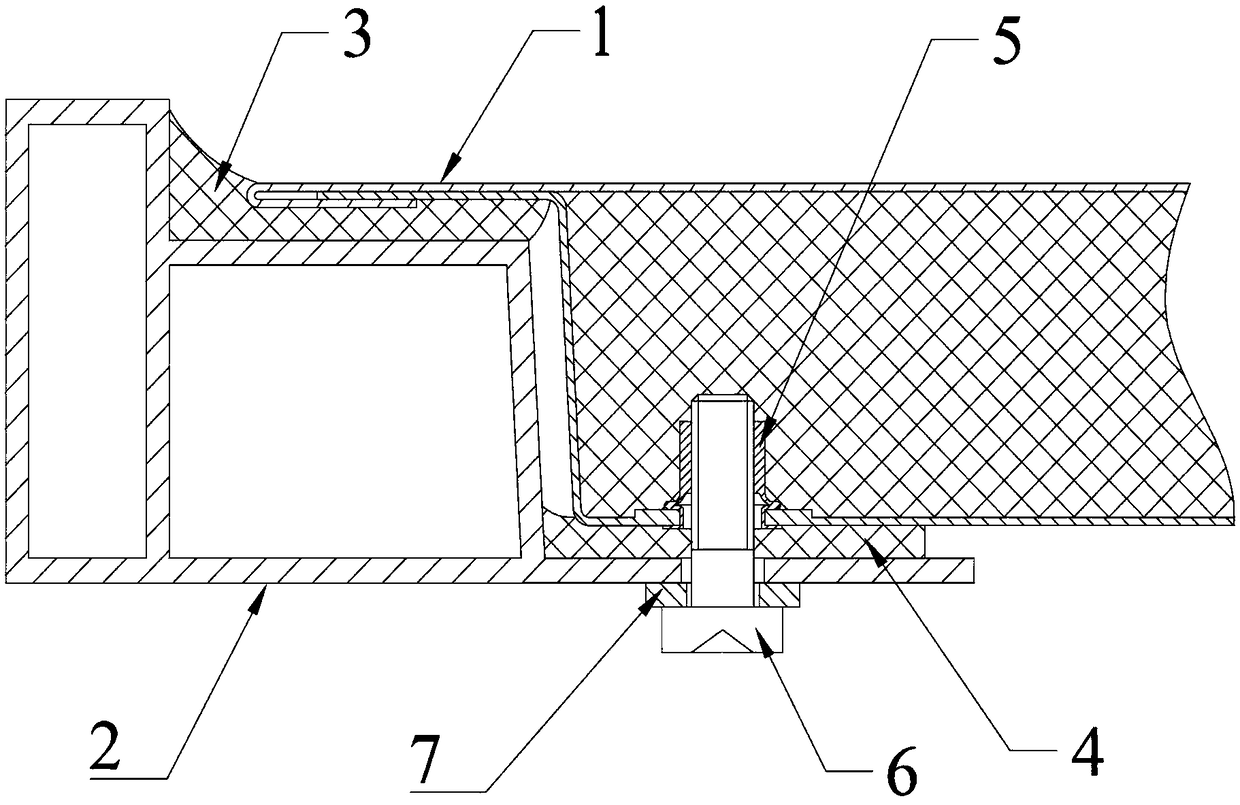
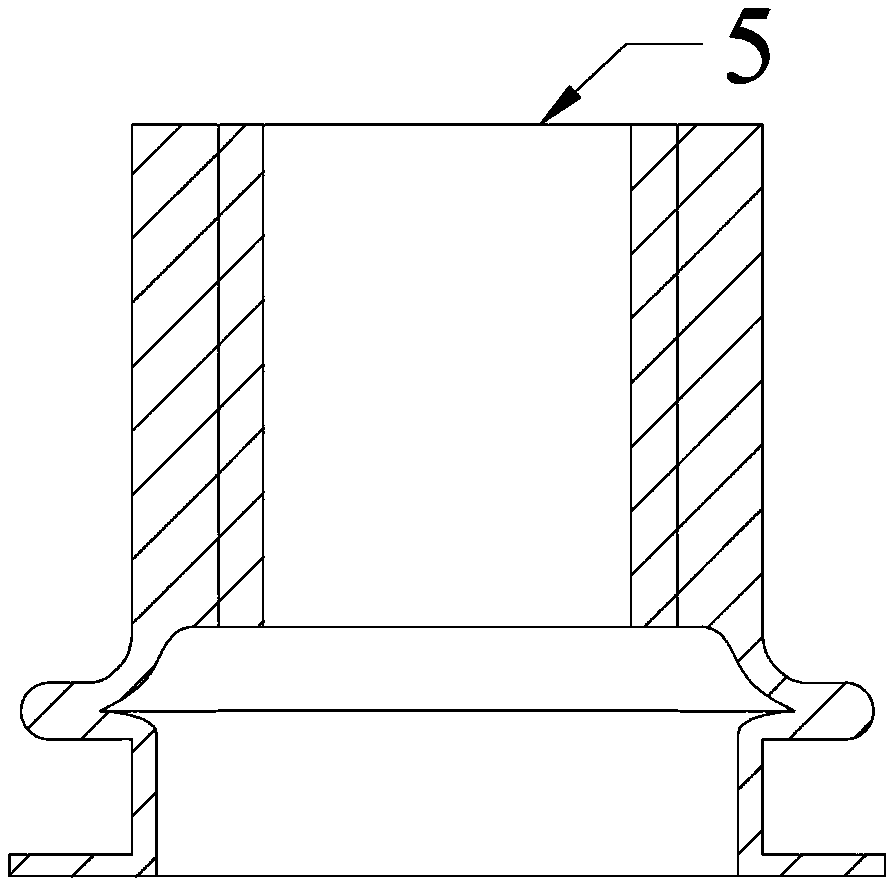
[0015] Such as figure 1 As shown, the riveting installation structure of a composite roof for a rail transit vehicle is a riveting installation structure for a composite roof for a rail transit vehicle, including a composite roof 1, a car body upper suspension beam 2, and a car body upper suspension beam 2 The upper surface of the inner side is a three-level stepped structure, the outer side is a metal profile with unequal sides and right angles, the lower surface of the side is a second-level stepped structure, and the first-level stepped structure on the lower surface of the side of the composite roof 1 is connected with the upper suspension beam 2 of the car body. The two-level stepped structure on the inner upper surface is bonded by sealant 3, and the elastic glue 4 is arranged between the first-level stepped structure on the lower surf...


PUM


Abstract

The invention discloses a bonding riveting installation structure of a composite top cover used for a rail traffic vehicle and belongs to the technical field of rail traffic vehicle light weight and passive safety. The structure comprises the composite top cover and a vehicle body upper suspension girder. The upper surface on the inner side of the vehicle body upper suspension girder is of a three-level stair structure, the outer side of the vehicle body upper suspension girder is made of a metal section of an inequilateral right-angle structure, the lower surface of the side edge of the composite top cover is of a two-level stair structure, a one-level stair structure of the lower surface of the side edge of the composite top cover and a two-level stair structure of the upper surface on the inner side of the vehicle body upper suspension girder are bonded through sealant, and elastic glue is arranged between the one-level stair structure of the lower surface of the side edge of the composite top cover and the three-level stair structure of the upper surface on the inner side of the vehicle body upper suspension girder which are connected through rivet nuts and bolts; and the rivetnuts are embedded in the one-level stair structure of the lower surface of the side edge of the composite top cover, and bolt holes matched with the rivet nuts are formed in the corresponding positions on the three-level stair structure of the vehicle body upper suspension girder. The structure is suitable for being applied and popularized in the technical field of rail traffic vehicle light weight and passive safety.

Description

technical field [0001] The invention belongs to the technical field of rail transit vehicle light weight and passive safety, and in particular relates to a rail transit vehicle structure. Background technique [0002] With the long-term and continuous development of my country's rail transit industry, traditional energy sources continue to decrease, especially for low-carbon environmental protection, energy saving, emission reduction, and safety of rail transit. It is particularly urgent to realize the lightweight and safety of the product structure. [0003] At present, the common joint forms of car body structure include welding, riveting and mechanical connection. Although these overlapping structures have the advantages of high strength and good reliability, there are large stress concentrations, poor sealing, many connecting parts, cumbersome manufacturing process, easy to generate vibration and noise, and require relatively high processing and installation accuracy. h...

Claims


Application Information

Patent Timeline
Patent Type & Authority Applications(China)
IPC IPC(8): B61D17/12
CPCB61D17/12Y02T30/00
Inventor 王明猛
Owner 成都西交轨道交通装备科技有限公司
Why Eureka
Try Eureka