Gravity reverse-supporting debris flow protective retaining wall and construction method thereof

An anti-support, debris flow technology, applied in gravity dams, hydraulic engineering, marine engineering and other directions, can solve the problems of not providing spring performance materials, not obtaining reasonable debris flow protection facilities, and inability to prove, and achieves good durability and ease of use. Promotion and application, simple effect of construction method

Inactive Publication Date: 2018-11-06
励春亚
View PDF4 Cites 3 Cited by
  • Summary
  • Abstract
  • Description
  • Claims
  • Application Information

AI Technical Summary

Problems solved by technology

The examples in the patent give the strength and performance parameters of the front gravity retaining wall, the rear gravity retaining wall, and various pipes, but do not give any performance materials of the spring, so it cannot be confirmed whether the spring is suitable for the debris flow protection retaining wall
[0009] It can be seen that there is still no reasonable debris flow protection facility, and the development of this product is very urgent

Method used


Image

  • Gravity reverse-supporting debris flow protective retaining wall and construction method thereof
  • Gravity reverse-supporting debris flow protective retaining wall and construction method thereof
  • Gravity reverse-supporting debris flow protective retaining wall and construction method thereof

Examples


Embodiment 1

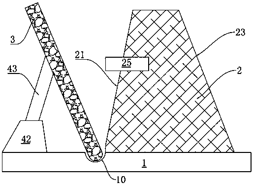
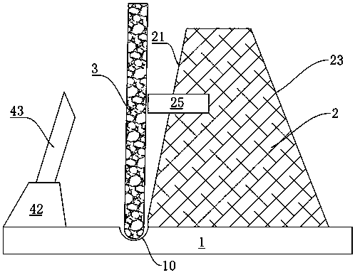
[0044] Such as figure 1 and figure 2 As shown, the gravity anti-supporting debris flow protective retaining wall of embodiment 1 includes a base 1, a dam body 2, a gravity plate 3 and a corner fixing seat arranged on the base 1.

[0045] Specifically, the base 1 is a bottom plate made of concrete with a strength grade not less than C40. The middle part of the base 1 is provided with a straight arc-shaped groove 10, the gravity plate 3 is placed upright on the groove 10, the dam body 2 is arranged on one side of the groove 10, and the angular position is fixed on the other side of the groove 10. seat.

[0046] The dam body 2 is provided with a water-facing slope 21 and a back-water slope 23 corresponding to each other. The facing slope 21 of the dam body 2 is located at the outermost part of the entire dam body 2, that is, the debris flow impact surface side, and is made of concrete with a strength grade not less than C40; the backwater slope 23 of the dam body 2 is located...

Embodiment 2

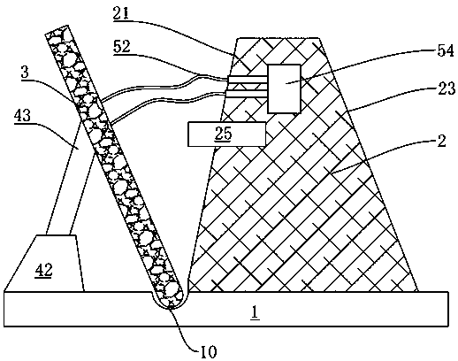
[0058] Such as image 3 and Figure 4 As shown, the gravity anti-supporting debris flow protective retaining wall of embodiment 2 is similar to the structure of embodiment 1, the difference is that embodiment 2 is also provided with a protection mechanism for connecting the gravity plate 3 and the dam body 2 .

[0059] Specifically, the protection mechanism includes a protection rope 52 with a certain strength and a protection rope fixing stake 54 . The protection rope fixing stake 54 is embedded in the middle and upper part of the dam body 2 . One end of the protection rope 52 is connected to the protection rope fixing stake 54 , and the other end of the protection rope 52 is connected to the middle and upper part of the gravity plate 3 . The protection rope 52 is in an unstressed state under normal conditions.

[0060] Preferably, in Embodiment 2, more than two protection ropes 52 are provided to ensure that the force on the protection ropes 52 is even. Moreover, even if...

Embodiment 3

[0071] Such as Figure 5 and Figure 6 As shown, the gravity anti-supporting debris flow protective retaining wall of embodiment 3 is similar to the structure of embodiment 2, the difference is that embodiment 3 is also provided with a trigger mechanism for connecting the corner fixing seat and the gravity plate 3 .

[0072] Specifically, the surface of the gravity plate 3 is perforated to form a safety installation hole 30 , and the end of the diagonal support rod 43 of the corner fixing seat is provided with a trigger screw 45 , and a safety washer 46 is provided on the trigger screw 45 . The trigger screw 45 is sleeved with a nut 47 , and the safety washer 46 is limited on the trigger screw 45 by the nut 47 . The safety installation hole 30 of the gravity plate 3 is mated with the trigger screw 45 of the inclined support rod 43 , and the safety gasket 46 is arranged in the safety installation hole 30 of the gravity plate 3 . The gravity plate 3 leans firmly against the co...


PUM


Abstract

The invention discloses a gravity reverse-supporting debris flow protective retaining wall which comprises a substrate, and a dam body, a gravity plate and an angular position fixing seat arranged onthe substrate, wherein a groove is formed in the substrate, the dam body is arranged on one side of the groove, and a positioning body is arranged on one side, close to the groove, of the dam body ina semi-embedded manner; the angular position fixing seat is arranged on the other side of the groove, and an oblique supporting rod facing the dam body obliquely upward is arranged on the angular position fixing seat; a side edge of the gravity plate is a round sliding side, the round sliding side of the gravity plate is matched with and is in butt joint to the groove of the substrate, and the gravity plate leans against the tail end of the oblique supporting rod. By taking self weight of the gravity plate as a buffering force, when the debris flow impact comes, the debris flow straightens thegravity plate to counteract a considerable part of debris flow impact by leaning the gravity plate against the angular positioning fixing seat, so that the gravity reverse-supporting debris flow protective retaining wall has a better anti-impact effect.

Description

technical field [0001] The invention relates to the field of mud-rock flow safety protection, in particular to a gravity anti-support mud-rock flow protective retaining wall and a construction method thereof. Background technique [0002] The dynamic pressure of mud-rock fluid slurry and the impact force of rocks are typical impact loads, which are characterized by a short action time (mostly measured in milliseconds, microseconds or even nanoseconds), but will generate extremely high pressure, eventually causing the medium Movement, material failure, and failure of entire structures. Under complex geological environment conditions, the traditional gravity retaining wall is subjected to special and changeable loads. Once the dam collapses during the debris flow outbreak, not only the expected prevention and control effect cannot be achieved, but the dam body and the solid materials it blocks will also be damaged. It will become the source of loose solid matter for debris fl...

Claims


Application Information

Patent Timeline
Patent Type & Authority Applications(China)
IPC IPC(8): E02B7/02E02B7/10
CPCE02B7/02E02B7/10
Inventor 不公告发明人
Owner 励春亚
Why Eureka
Try Eureka