

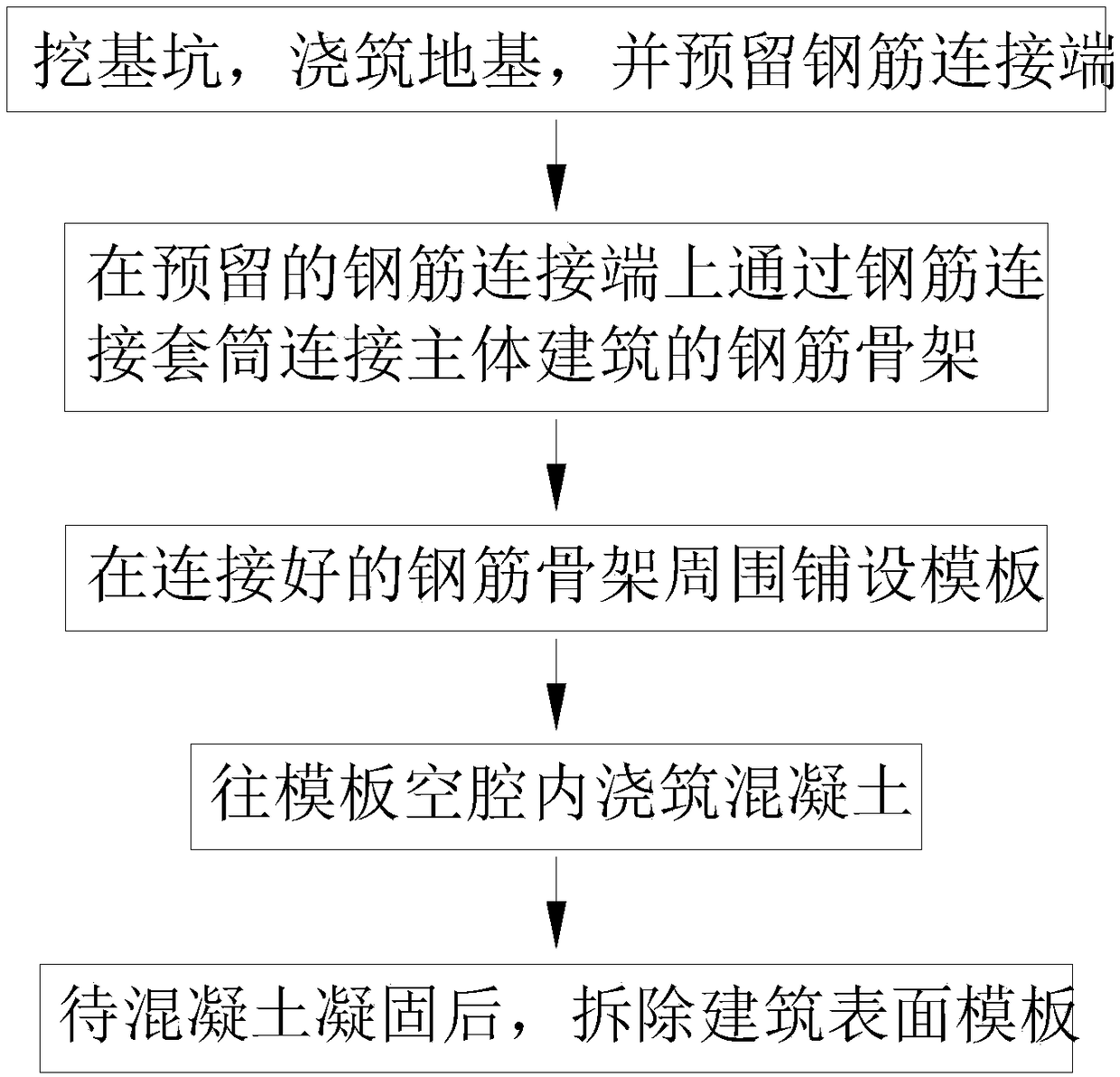
Method for improving building construction efficiency
A technology of construction and efficiency, applied in the processing of building materials, construction, building components, etc., can solve the problems of increased cost, inability to adjust the connection angle of steel bars, cumbersome operation, etc., and achieve the effect of increasing the distance.
- Summary
- Abstract
- Description
- Claims
- Application Information
AI Technical Summary
Problems solved by technology
Method used
Image

Examples
Embodiment approach
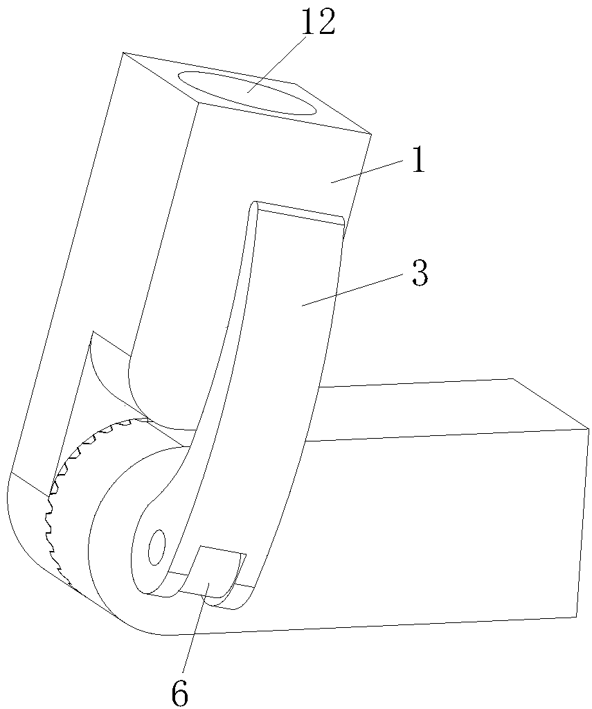
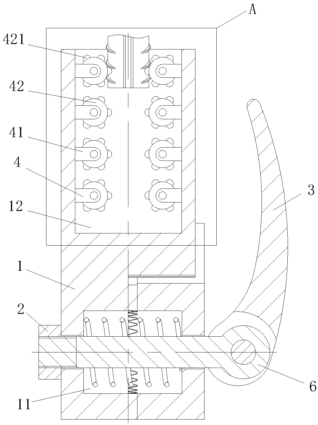
[0036] As the first embodiment of the clamping module 4 in the present invention, the clamping module 4 includes a support plate 41, a No. 1 roller 42, and a ratchet pawl device. The No. 1 cylindrical hole 12 is provided with two sets of support plates 41 One end of the support plate 41 is fixedly connected in the No. 1 cylindrical hole 12, and the other end of the support plate 41 is connected to the No. 1 roller 42 through a ratchet pawl device; During use, the steel bar is inserted in the No. 1 cylindrical hole 12, and the arc-shaped protrusion on the surface of the steel bar pushes the arc-shaped tooth 421 on the cylindrical surface of the No. 1 roller 42 to move, and the arc-shaped tooth 421 drives the No. 1 roller 42 to rotate. Both sides of the steel bar are squeezed by two groups of No. 1 rollers 42, and because the No. 1 rollers 42 are connected on the support plate 41 through the ratchet pawl device, the steel bar can only be inserted from the No. 1 cylindrical hole 1...
PUM
 Abstract
Description
Claims
Application Information