
Composite tunnel fireproof door, fireproof door system and preparation method

A technology of tunnel fire doors and composite materials, applied in the field of tunnel fire doors, can solve the problems of not fully considering the influence of piston wind, door body corrosion, fire door corrosion, etc., to improve wind pressure resistance and anti-dumping ability, and ensure overall connection Strength, the effect of ensuring fire performance

Pending Publication Date: 2018-11-06
CHINA RAILWAY SIYUAN SURVEY & DESIGN GRP
View PDF7 Cites 8 Cited by
  • Summary
  • Abstract
  • Description
  • Claims
  • Application Information

AI Technical Summary

Problems solved by technology

[0003] At present, conventional fire doors are installed in the tunnel communication channel and the rainwater pump room. According to the actual operation situation, it is found that the conventional fire doors have been corroded, deformed, fallen off or even dumped, and serious safety accidents have occurred
After research, it is found that the main reason for the above situation is the lack of understanding of the impact of the piston wind on the fire door in the tunnel section when designing the fire door, and the impact of the piston wind on the door body is not fully considered.
Due to the effect of long-term piston wind, although conventional fire doors can meet the fire protection requirements, their overall strength is not enough to withstand the effect of long-term piston wind, and it is affected by the humid environment of the tunnel, the door body is seriously corroded, and the service life is greatly reduced

Method used


Image

  • Composite tunnel fireproof door, fireproof door system and preparation method
  • Composite tunnel fireproof door, fireproof door system and preparation method
  • Composite tunnel fireproof door, fireproof door system and preparation method

Examples


Embodiment Construction

[0033] In order to make the object, technical solution and advantages of the present invention clearer, the present invention will be further described in detail below in conjunction with the accompanying drawings and embodiments. It should be understood that the specific embodiments described here are only used to explain the present invention, not to limit the present invention. In addition, the technical features involved in the various embodiments of the present invention described below can be combined with each other as long as they do not constitute a conflict with each other.

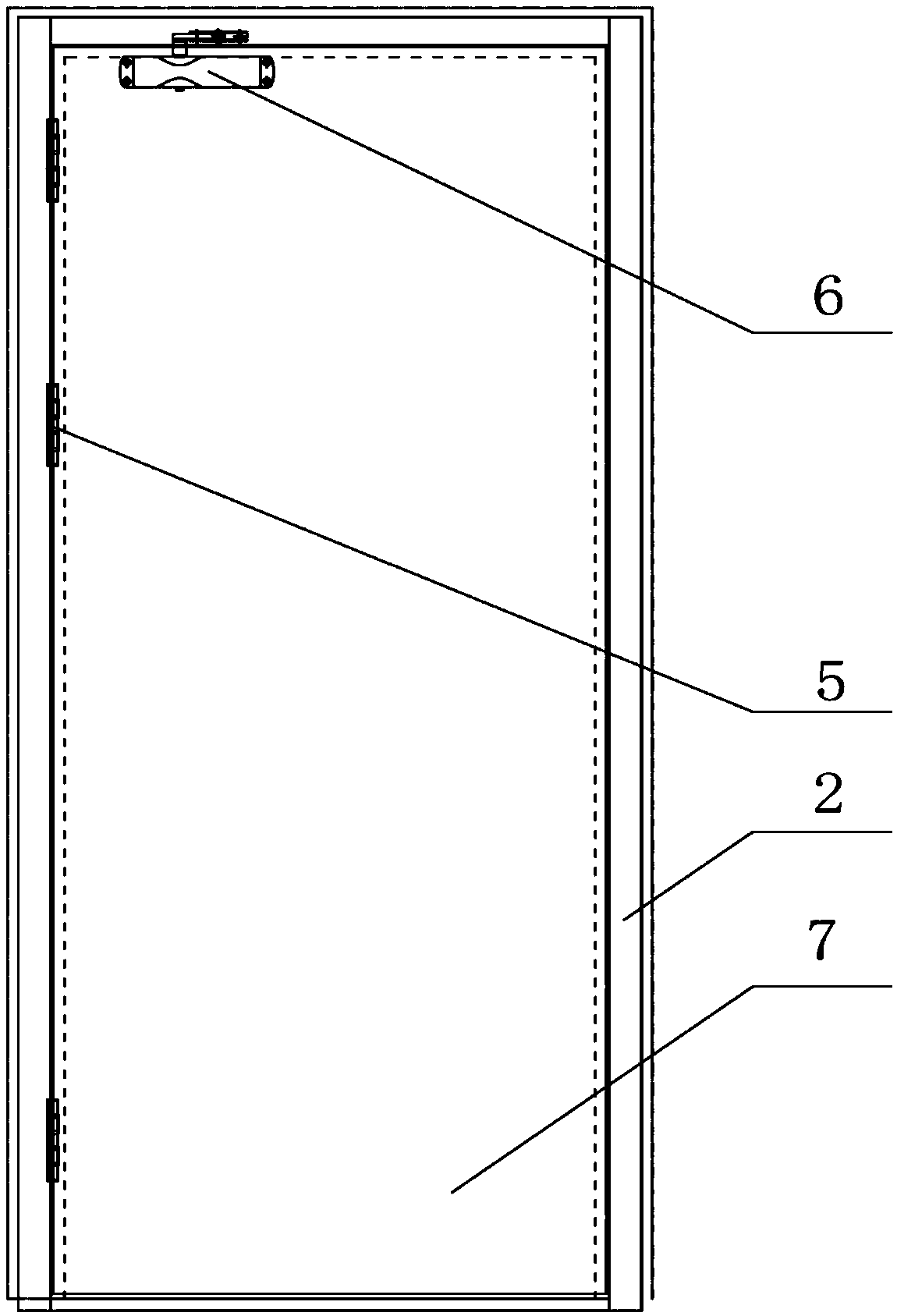
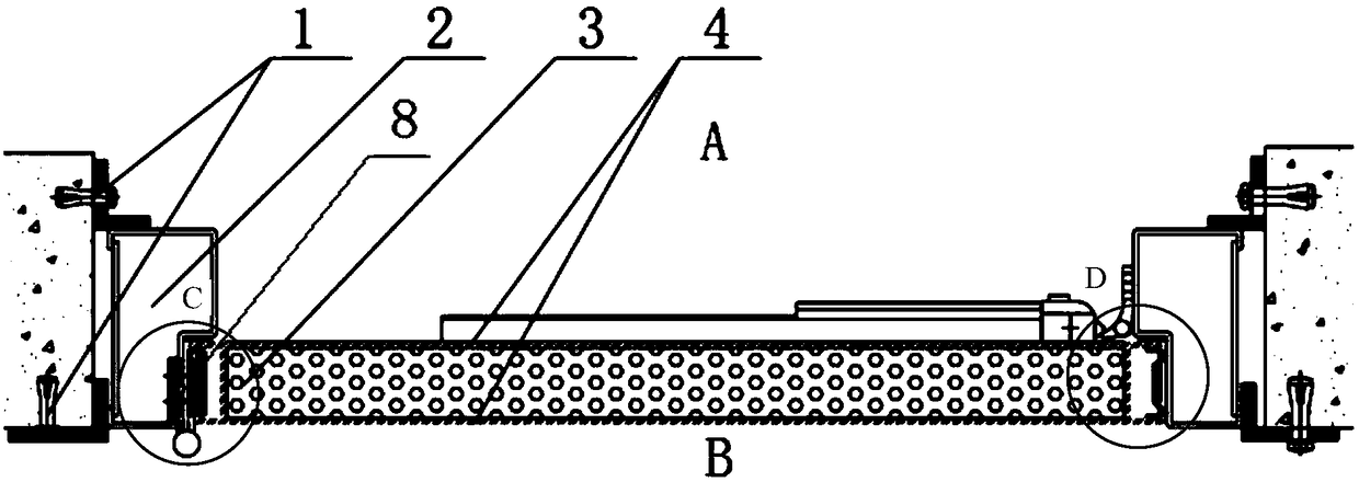
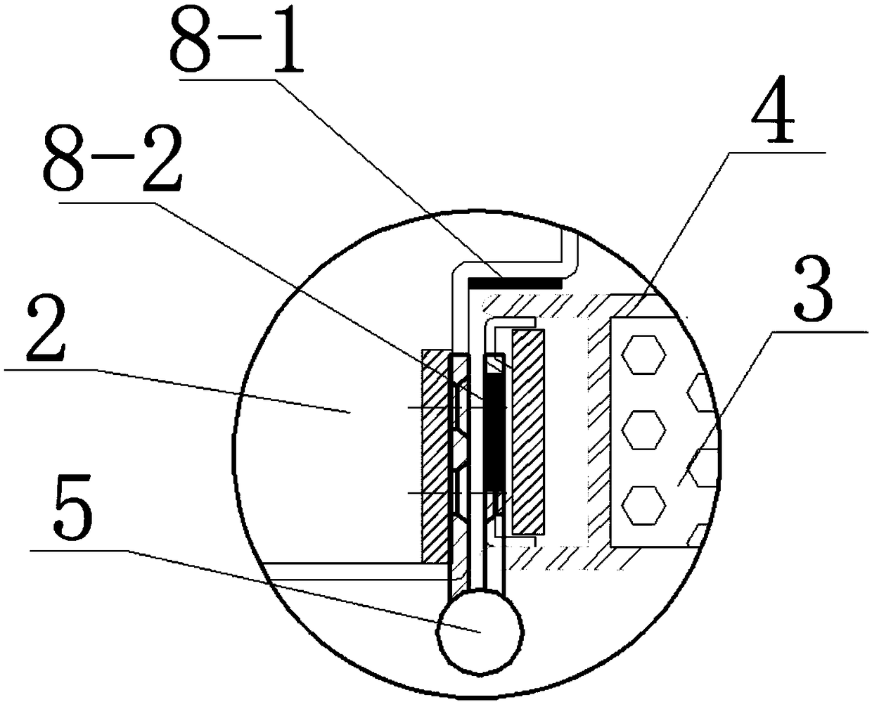
[0034] Such as figure 1 As shown, a composite material tunnel fire door 7 provided by the embodiment of the present invention is a core component for fire protection, explosion resistance, wind pressure resistance, fatigue resistance, and aging resistance in the tunnel protective door system. A three-layer composite structure composed of a fireproof layer sandwiched between the surface layer, i...


PUM

PropertyMeasurementUnit
thicknessaaaaaaaaaa
thicknessaaaaaaaaaa
thicknessaaaaaaaaaa

Abstract

The invention belongs to the field of tunnel fireproof doors, and particularly discloses a composite tunnel fireproof door, a fireproof door system and a preparation method. The composite tunnel fireproof door is of a three-layer composite structure composed in the mode that a fireproof layer is sandwiched between two composite surface layers. The fireproof layer is made of a fireproof heat-resistant material, and the composite surface layers are made of high-strength corrosion-resistant materials. The fireproof door system comprises a door frame and the fireproof door mounted in the door frame, and the fireproof door is mounted in a tunnel doorway through the door frame. The preparation method comprises the steps that the fireproof layer is prepared, and a resin solution is prepared; theresin solution is smeared on the two surfaces of the fireproof layer to prepare fireproof layer prepreg; glass fibers are soaked in the resin solution and then dried to prepare prepreg; the prepreg issuperimposed on the two surfaces of the fireproof layer prepreg and then preheated and subjected to heat preservation to obtain a raw material plate; and the raw material plate is hot-pressed to prepare the composite tunnel fireproof door. The requirements of explosion resistance, wind pressure resistance, fatigue resistance and corrosion resistance are met while the fireproof performance is achieved.

Description

technical field [0001] The invention belongs to the field of tunnel fire doors, and more specifically relates to a composite material tunnel fire door, a fire door system and a preparation method. Background technique [0002] Rail transit single-line tunnels, such as subway interval tunnels, are provided with interval communication passages, which need to be equipped with fire doors. In addition, to ensure the safety of the equipment in the rainwater pumping room in the tunnel, the subway rainwater pumping room also needs to be equipped with fire doors. [0003] At present, conventional fire doors are installed in the tunnel communication channel and the rainwater pump room. According to the actual operation situation, it is found that the conventional fire doors have been corroded, deformed, fallen off or even dumped, and serious safety accidents have occurred. After research, it is found that the main reason for the above situation is the lack of understanding of the impa...

Claims


Application Information

Patent Timeline
Patent Type & Authority Applications(China)
IPC IPC(8): E21F17/12B32B27/06B32B9/00B32B9/04B32B17/04B29C65/02
CPCE21F17/12B29C65/02B32B5/02B32B9/00B32B9/045B32B27/06B32B2419/00B32B2250/40B32B2260/021B32B2260/046B32B2255/26B32B2262/101B32B2307/3065B32B2307/7145B32B2307/552
Inventor 李成洋张浩耿明许克亮刘辉张俊岭周明翔倪琍郑燕游鹏辉
Owner CHINA RAILWAY SIYUAN SURVEY & DESIGN GRP
Learn More