Exhaust gas bypass turbine machine with turbine end being provided with gas inlet mixing device
A turbine and exhaust gas technology, applied in the direction of mechanical equipment, engine components, machines/engines, etc., can solve the problems of turbine 11 impact, affecting turbine reliability, affecting customer driving comfort, etc., to reduce airflow impact and reduce BPF noise and casing thermal stress concentration, improving reliability and turbine efficiency
- Summary
- Abstract
- Description
- Claims
- Application Information
AI Technical Summary
Problems solved by technology
Method used
Image

Examples
Embodiment 1
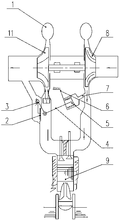
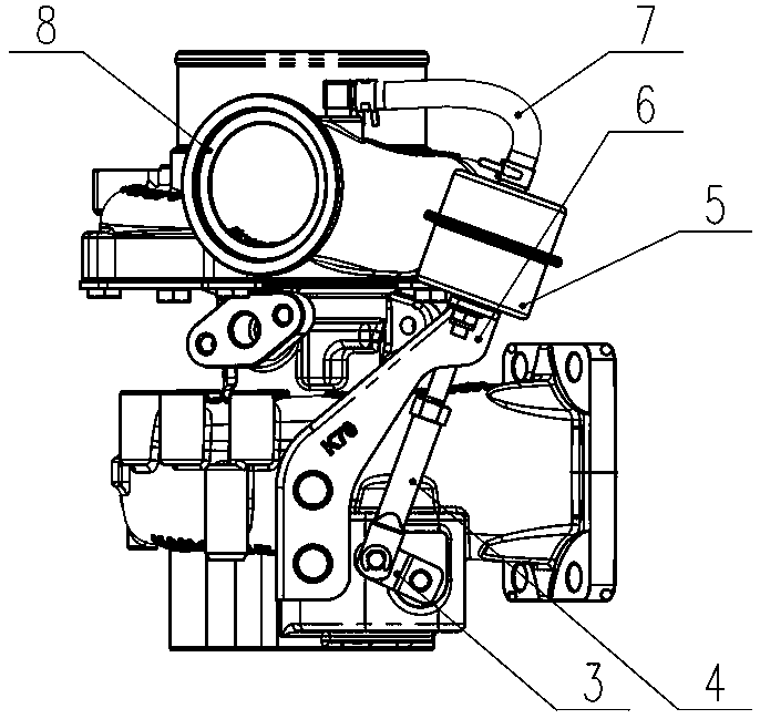
[0032] like Figure 5 , Image 6 and Figure 7 Commonly shown, the wastegate turbine with a throat mixing device at the vortex end includes a turbine 11 and a turbine casing 12, and the turbine casing 12 is provided with a first throat 16, a second throat 18 and a vaneless nozzle 10 , and also includes a waste gas bypass passage communicated with the second throat 18, and a bypass purge valve 2 is provided between the second throat 18 and the waste gas bypass passage. The distribution radius of the first throat 16 and the second throat 18 is increased, and at the same time, the outer diameter of the vaneless nozzle 10 is increased, and the volume of the vaneless nozzle 10 is increased. Before the turbine exhaust gas enters the turbine 11, the gas is firstly mixed in the vaneless nozzle 10. Since the volume of the vaneless nozzle 10 increases, the space for mixing the exhaust gas increases, the effect of exhaust gas mixing is good, and the mixing is more uniform. The mixed e...
Embodiment 2
[0034] like Figure 8 and Figure 9 Commonly shown, the wastegate turbine with a throat mixing device at the vortex end includes a turbine 11 and a turbine casing 12, and the turbine casing 12 is provided with a first throat 16, a second throat 18 and a vaneless nozzle 10 , and also includes a waste gas bypass passage communicated with the second throat 18, and a bypass purge valve 2 is provided between the second throat 18 and the waste gas bypass passage. Adjust the distribution radius of the first throat 16 on the turbine shell 12, set the first throat 16 as a front throat, and the exhaust gas passing through the first throat 16 enters the vaneless nozzle earlier than the exhaust gas passing through the second throat 18 10. When the exhaust gas enters the first throat 16 of the turbine shell 12, on the one hand, it is mixed with the gas at the second throat 18 to reduce the impact of the exhaust gas on the blades of the turbine 11; 11 blades do work. Through the arrange...
Embodiment 3
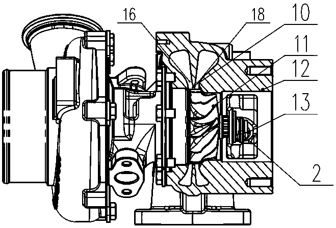
[0036] like Figure 10 , Figure 11 and Figure 12 Commonly shown, the wastegate turbine with a throat mixing device at the vortex end includes a turbine 11 and a turbine casing 12, and the turbine casing 12 is provided with a first throat 16, a second throat 18 and a vaneless nozzle 10 , and also includes a waste gas bypass passage communicated with the second throat 18, and a bypass purge valve 2 is provided between the second throat 18 and the waste gas bypass passage. Adjust the distribution radius of the second throat 18 on the turbine casing 12 , the second throat 18 is a front throat, and the exhaust gas in the second throat 18 enters the vaneless nozzle 10 earlier than the exhaust gas in the first throat 16 .
[0037]When the exhaust gas enters the second throat 18 of the turbine housing 12, when the bypass bleed valve 2 is closed, the first throat 16 and the second throat 18 are arranged one after the other, so that the air flow flows through the vaneless nozzle. I...
PUM
 Abstract
Description
Claims
Application Information
 - R&D
- Intellectual Property
- Life Sciences
- Materials
- Tech Scout
- Unparalleled Data Quality
- Higher Quality Content
- 60% Fewer Hallucinations
Browse by: Latest US Patents, China's latest patents, Technical Efficacy Thesaurus, Application Domain, Technology Topic, Popular Technical Reports.
© 2025 PatSnap. All rights reserved.Legal|Privacy policy|Modern Slavery Act Transparency Statement|Sitemap|About US| Contact US: help@patsnap.com