
Air sealing structure and method for thrust and guiding bearings of water-turbine generator set

A generator set and hermetic sealing technology, applied in hydropower, engine components, machines/engines, etc., can solve problems such as poor sealing effect, seal wear, damage, etc.

Active Publication Date: 2018-11-06
CHINA YANGTZE POWER
View PDF7 Cites 4 Cited by
  • Summary
  • Abstract
  • Description
  • Claims
  • Application Information

AI Technical Summary

Problems solved by technology

Turbine oil is in contact with the thrust head of the high-speed rotating hydro-generator set and the outer wall of the mirror plate, splashes or hits under the action of centrifugal force, continuously forms gaseous oil mist, and overflows outward through the contact seal between the oil tank and the rotating thrust head, and the oil mist The wind enters the wind circulation system of the generator along with the rotor arm of the generator, and condenses on the surface of the generator wire rod, air cooler and bearing cap equipment and the ground of the upper wind tunnel to form oil pollution, pollute the surface of the equipment, or cause insulation of electrical components such as stator wire rods decrease, seriously endangering the safe and stable operation of the unit
[0003] The derivation bearing seal of the semi-umbrella hydro-generator set in service mainly uses special wear-resistant materials to adopt a contact seal structure between the oil tank cover and the thrust head to prevent the oil mist from leaking out of the bearing, but this structure has some unavoidable disadvantages: First, the swing of the unit prevents the contact sealing material from sticking to the sealing surface all the time, and there is always the possibility of oil mist leakage; second, the long-term operation of the unit causes seal wear or damage, which makes the sealing effect worse; third, for Large-scale air-cooled generator set, the generator rotor rotates in the wind tunnel to drive the air flow, and generates a large wind speed above the thrust oil tank, forming a negative pressure and accelerating the leakage of oil mist

Method used


Image

  • Air sealing structure and method for thrust and guiding bearings of water-turbine generator set
  • Air sealing structure and method for thrust and guiding bearings of water-turbine generator set
  • Air sealing structure and method for thrust and guiding bearings of water-turbine generator set

Examples


Embodiment Construction

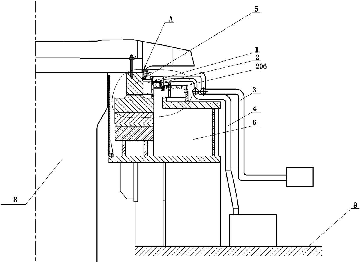
[0036] like Figure 1-6 As shown in the figure, a hydro-generator set derives an air-tight structure of the bearing, which mainly includes a rotating fan blade 1, an inner oil tank cover 2, an air supply system 3, and an oil mist absorption system 4. specifically:

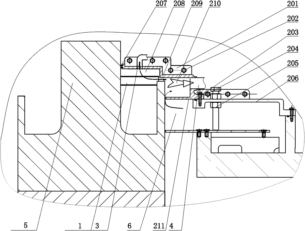
[0037] The rotating fan blade 1 is a backward curved blade shape, and the bottom is provided with a deflector plate 10, a total of 36 pieces (calculated according to the simulation). 36 pieces of rotating fan blades 1 are evenly distributed and welded in the groove of the thrust head 5. During the rotation of the large axis of the random group, a radial high-speed airflow is formed in the radial flow channel 209 .

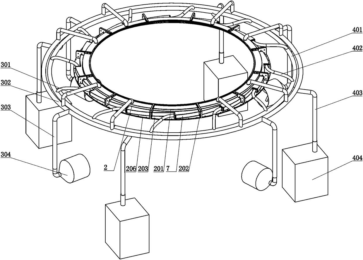
[0038] The inner oil tank cover 2 is composed of 12 split structures 201 , each split structure 201 is sealed and spliced ​​into a complete circle using connecting bolts 202 . The inner oil tank cover 2 is fixed on the original outer oil tank cover 206 by fastening bolts 203, and a first gasket 204 is...


PUM


Abstract

The invention discloses an air sealing structure and method for thrust and guiding bearings of a water-turbine generator set. The air sealing structure comprises an inner oil tank cover with the radial inner side connected with a thrust head in a sealed mode and with the radial outer side connected with an outer oil tank cover in a sealed mode. An air flow channel is formed at the boundary betweenthe inner oil tank cover and a thrust oil tank and comprises an air blade chamber, a radial flow channel and an oil mist collecting box, wherein the air blade chamber is located in a thrust head groove, and a plurality of rotating air blades are distributed in the air blade chamber in the circumferential direction and rotate together with a unit to generate radial air flow. The radial flow channel is transversely arranged and used for conveying high-speed air flow to the oil mist collecting box. The oil mist collecting box communicates with an oil mist absorption system, so that oil mist in the oil mist collecting box is discharged and collected. According to the air sealing structure for the thrust and guiding bearings of the water-turbine generator set, oil mist in the oil tank can be effectively prevented from being discharged outside.

Description

technical field [0001] The invention relates to a hydroelectric generating set, in particular to a structure and method for deriving a bearing air seal of a hydroelectric generating set. Background technique [0002] The thrust bearing and the lower guide bearing are arranged under the rotor of the semi-umbrella hydro-generator set, and are assembled in an oil tank, called the derivation bearing, which is used to bear the weight of the rotating part of the unit and limit its swing. Turbine oil is injected into the derivation bearing oil groove for lubrication, cooling and rust prevention. Turbine oil is in contact with the thrust head of the high-speed rotating hydro-generator set and the outer wall of the mirror plate, splashes or hits under the action of centrifugal force, continuously forms gaseous oil mist, and overflows outward through the contact seal between the oil tank and the rotating thrust head, and the oil mist The wind enters the wind circulation system of the...

Claims


Application Information

Patent Timeline
IPC IPC(8): F03B11/00F03B11/06
CPCF03B11/00F03B11/006F03B11/06Y02E10/20
Inventor 张谷雄苏纪成邓阳兵张承俊陈晓龙刘德新井弦伟
Owner CHINA YANGTZE POWER
Features
  • Generate Ideas
  • Intellectual Property
  • Life Sciences
  • Materials
  • Tech Scout
  • Unparalleled Data Quality
  • Higher Quality Content
  • 60% Fewer Hallucinations
Learn More