
Pulse resistor and method for adjusting the resistance of the pulse resistor

A technology of pulse resistance and resistance adjustment, used in resistors, resistor manufacturing, thick film resistors, etc.

Inactive Publication Date: 2018-11-06
CHINA ZHENHUA GRP YUNKE ELECTRONICS
View PDF5 Cites 0 Cited by
  • Summary
  • Abstract
  • Description
  • Claims
  • Application Information

AI Technical Summary

Problems solved by technology

[0003] The purpose of the present invention is to provide a pulse resistance and a method for adjusting the resistance of the pulse resistance, which solves the problem in the prior art that there are obvious hot spots of the pulse resistance during the resistance adjustment process

Method used


Image

  • Pulse resistor and method for adjusting the resistance of the pulse resistor
  • Pulse resistor and method for adjusting the resistance of the pulse resistor
  • Pulse resistor and method for adjusting the resistance of the pulse resistor

Examples


Embodiment

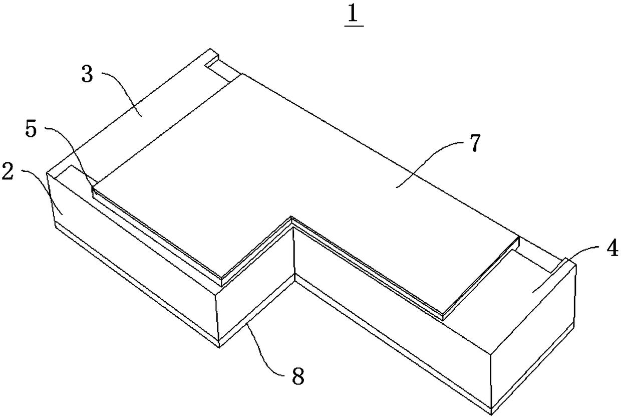
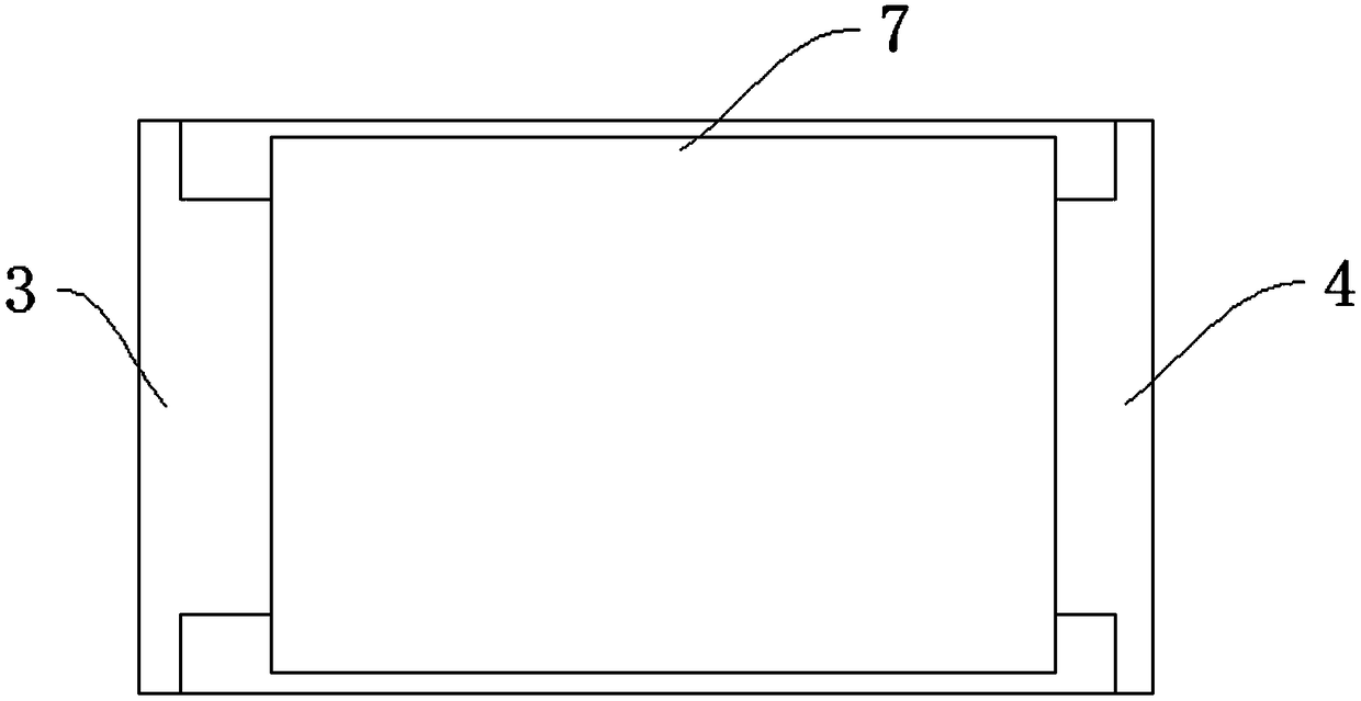
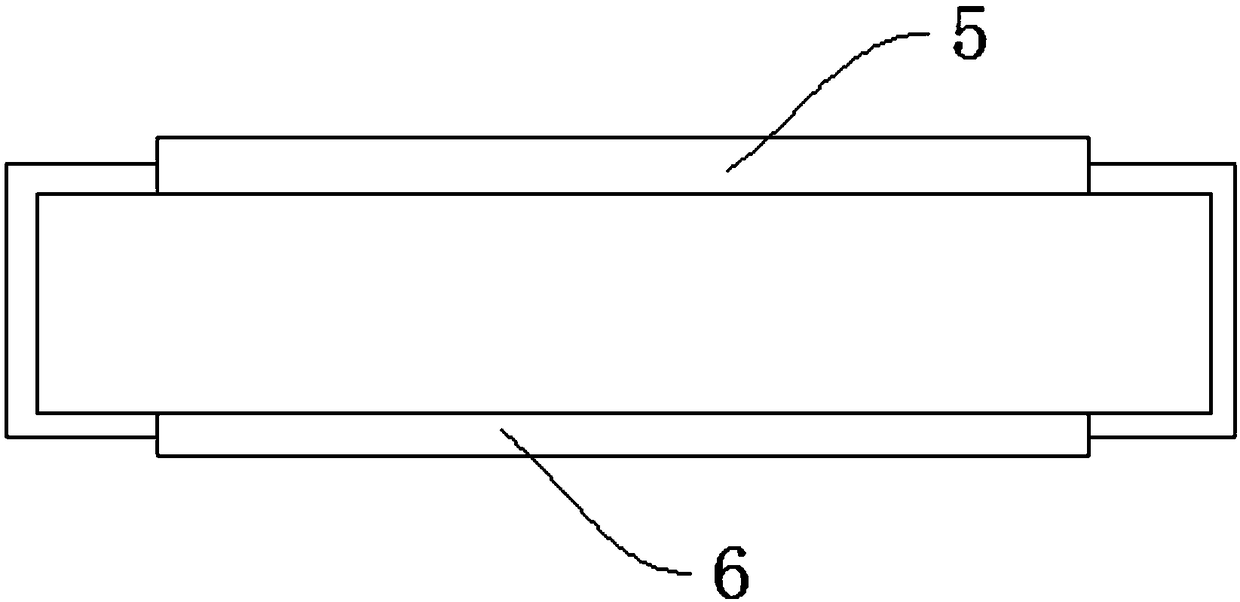
[0042] Please refer to figure 1 , with reference to Figure 2 to Figure 4 , the embodiment of the present invention provides a pulse resistor 1, which adopts a pulse resistance adjustment method to adjust resistance.

[0043] Wherein, the pulse resistor 1 includes a ceramic base 2, a first electrode 3, a second electrode 4, a first resistor 5, a second resistor 6, a first glass layer 7 and a second glass layer 8; the ceramic base 2 has a relatively The first side end and the second side end, the first electrode 3 is covered on the first side end, and the second electrode 4 is covered on the second side end; the ceramic substrate 2 has an opposite first surface and a second surface, and the second electrode 4 is covered on the second side end; A resistor body 5 is installed on the first surface, and a second resistor body 6 is installed on the second surface; the first glass layer 7 is installed on the first resistor body 5, and the second glass layer 8 is installed on the sec...


PUM


Abstract

The invention relates to a pulse resistor and a method for adjusting the resistance of the pulse resistor, which relates to the technical field of electronic products. S1, lengthening the length and width of the first resistor and the second resistor, and widening the width of the first electrode and the second electrode; S2, performing screen production on pulse resistor according to the design positive diagram; S3, printing the produced screen plate with intermediate parameters, and firing the first resistor and the second resistor at 850 DEG C; S4, printing a first glass layer and a secondglass layer on the fired first resistor and a second resistor substrate, and firing the first glass layer and the second glass layer at 600 DEG C; S5, designing U-shaped laser grooving cutting parameters according to the negative resistance degree and resistance precision of the pulse resistance; S6, setting the laser resistance adjustment parameter according to the resistance value of the pulse resistor, and adjusting the resistance. The pulse resistor made by the method has strong heat dissipation ability.

Description

technical field [0001] The invention relates to the technical field of electronic products, and in particular to a pulse resistance and a method for adjusting the resistance of the pulse resistance. Background technique [0002] The pulse resistance requires that the products have good high-frequency characteristics and pulse absorption characteristics, so ordinary L-shaped laser resistance adjustment cannot be used in the manufacturing process. For thick film resistors, L-type laser trimming is usually used, and L-type laser trimming has hot spots in the working process. Anti-pulse resistors need to absorb a lot of energy in a short time. If there are hot spots, it is easy to burn out the product. , so the L-type laser resistance adjustment method cannot be used for the resistance adjustment method of the anti-pulse resistance. Contents of the invention [0003] The object of the present invention is to provide a pulse resistance and a method for adjusting the resistance...

Claims


Application Information

Patent Timeline
Patent Type & Authority Applications(China)
IPC IPC(8): H01C7/00H01C17/065
CPCH01C7/003H01C17/065
Inventor 王丹琴陈传庆叶萍韩玉成
Owner CHINA ZHENHUA GRP YUNKE ELECTRONICS
Learn More