Motor rotor and permanent magnet motor

A technology of motor rotor and permanent magnet, which is applied to magnetic circuits, electrical components, electromechanical devices, etc., can solve the problems of motor performance degradation, permanent magnet loss of magnetism, and motor inoperability, etc., to improve reluctance, reduce inner magnetic flux leakage, The effect of reducing the cost of the motor

Inactive Publication Date: 2018-11-06
ZHUHAI GREE REFRIGERATION TECH CENT OF ENERGY SAVING & ENVIRONMENTAL PROTECTION
View PDF6 Cites 1 Cited by
  • Summary
  • Abstract
  • Description
  • Claims
  • Application Information

AI Technical Summary

Problems solved by technology

[0003] In the tangential permanent magnet motor of the prior art, since the permanent magnets of the rotor are radially arranged, a part of the permanent magnets is deeply buried inside the rotor, an external magnetic field is applied to the rotor, and when the permanent magnets of the rotor are magnetized, the inner side of the permanent magnets will The passage makes it difficult for the magnetizing magnetic field to enter the part of the rotor close to the rotating shaft, and the part of the permanent magnet near the rotating shaft cannot be magnetized to reach saturation, which will easily lead to a decrease in motor performance, or even loss of magnetization of the permanent magnet, and the motor cannot run

Method used


Image

  • Motor rotor and permanent magnet motor
  • Motor rotor and permanent magnet motor
  • Motor rotor and permanent magnet motor

Examples


Embodiment Construction

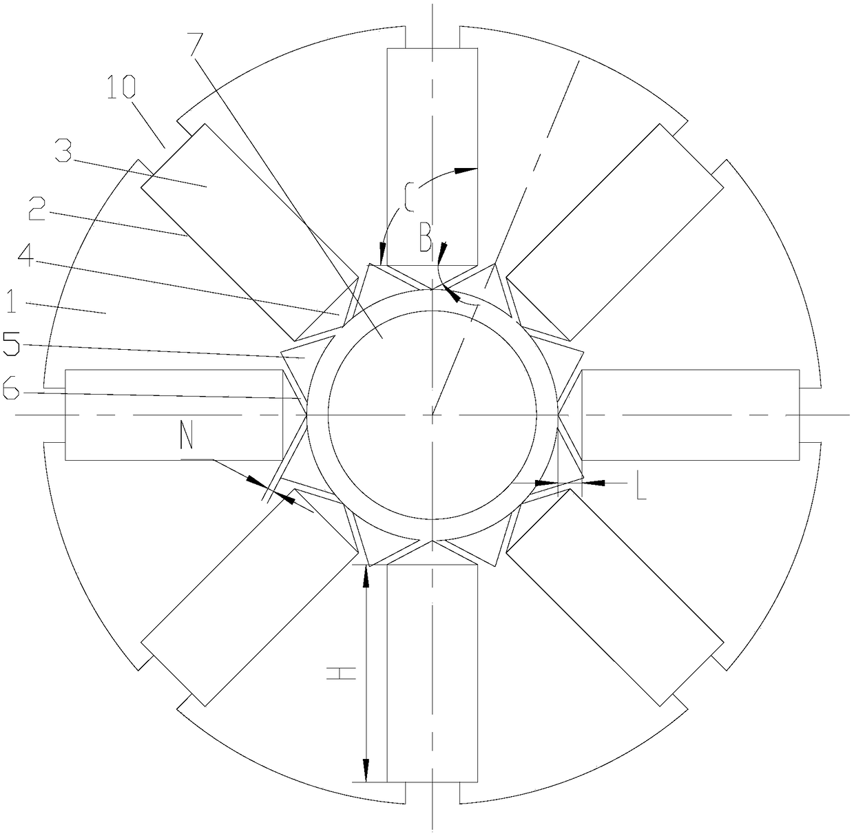
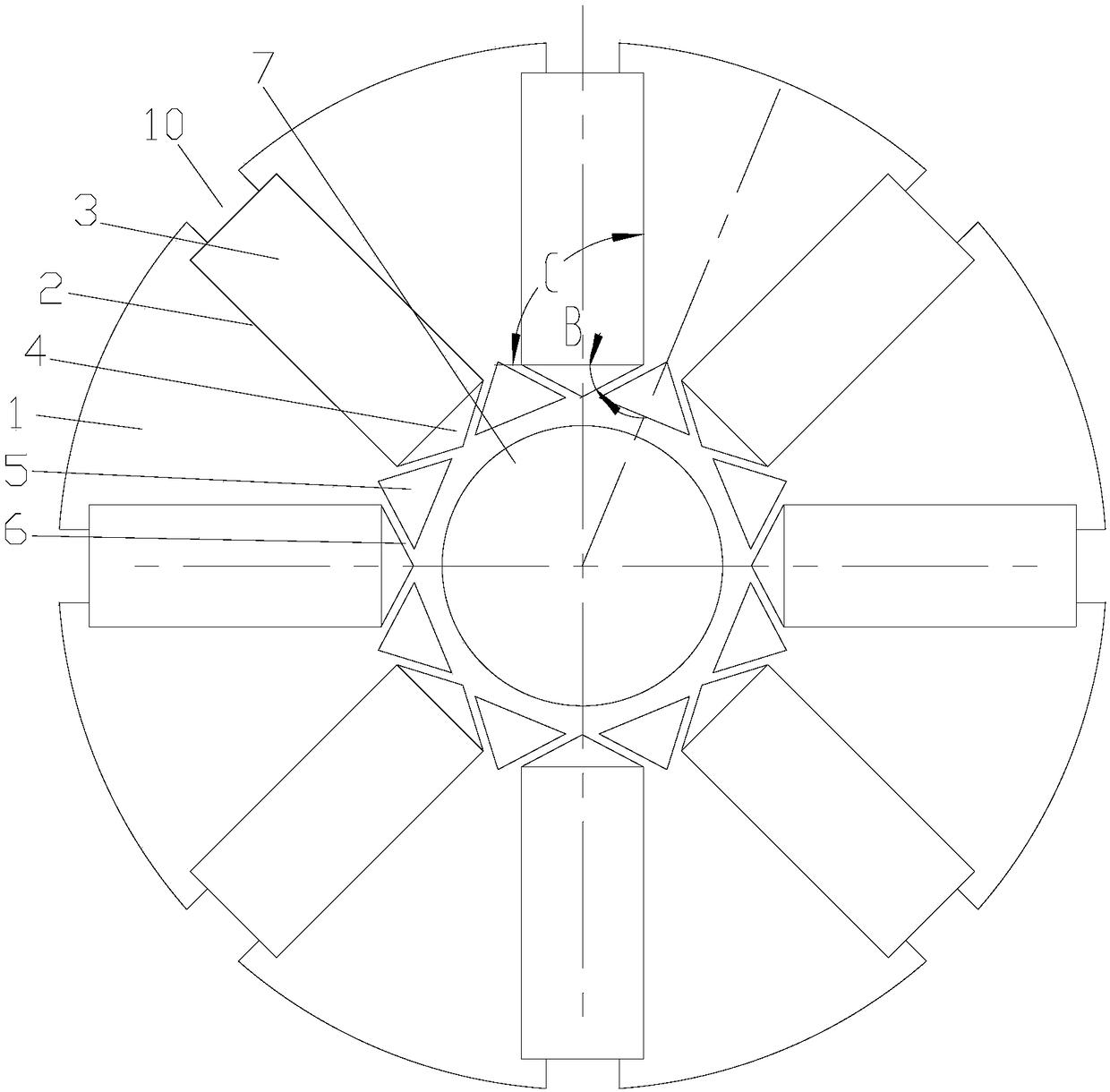
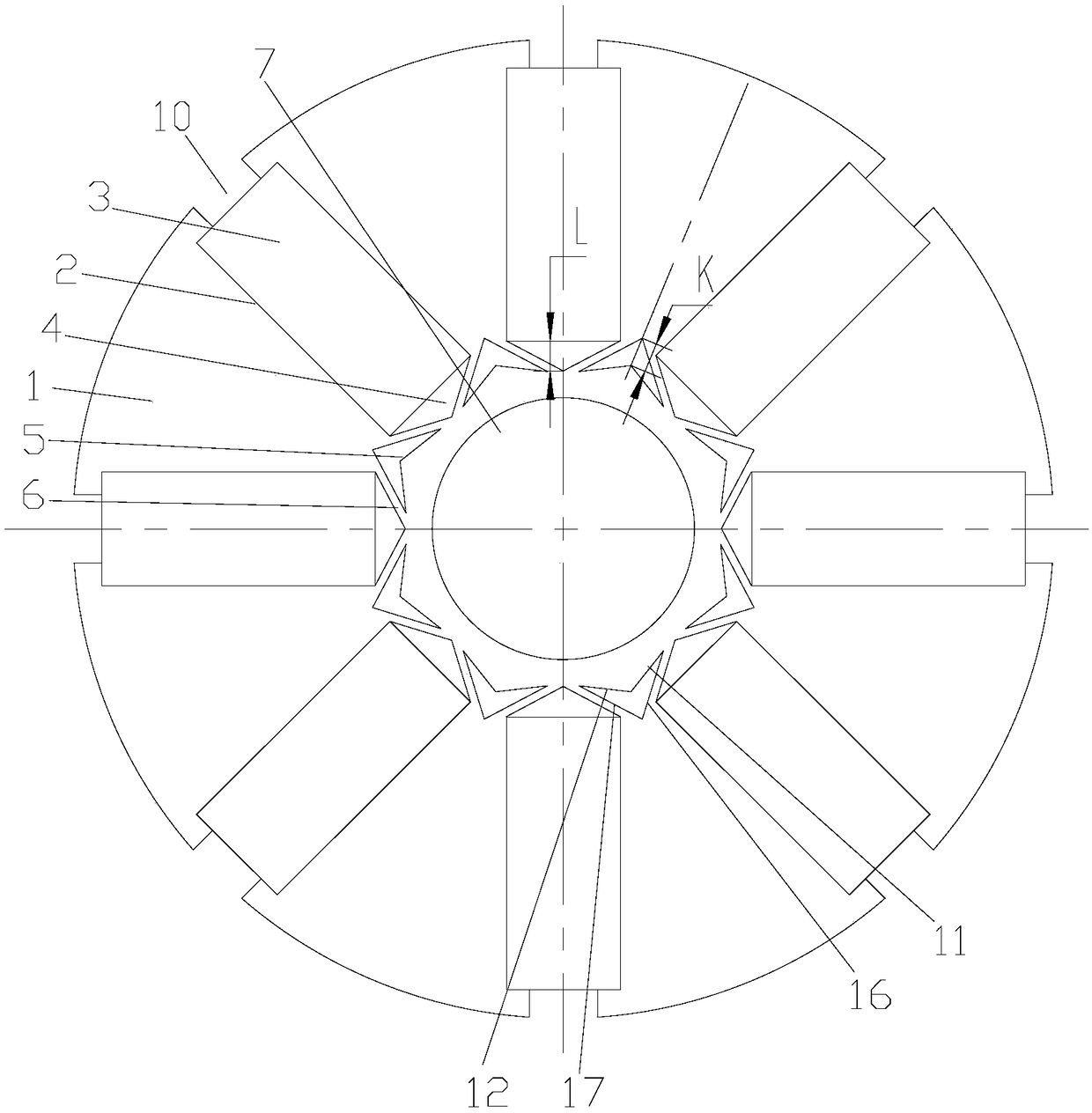
[0051] see in conjunction Figures 1 to 13 As shown, according to an embodiment of the present invention, the motor rotor includes a rotor iron core 1, and the rotor iron core 1 is provided with a plurality of permanent magnet slots 2 along the circumferential direction, and permanent magnets 3 are arranged in the permanent magnet slots 2, and the permanent magnet slots 2 Magnetic isolation slots 4 are provided on the inner side, and magnetic isolation holes 5 are arranged at intervals between two adjacent magnetic isolation slots 4, and a straight magnetic isolation bridge 6 is formed between the magnetic isolation slots 4 and the magnetic isolation holes 5. There is a preset angle between the bridge 6 and the center line of the magnetic pole. Preferably, each permanent magnet slot 2 is provided with a permanent magnet 3 , the permanent magnet 3 is magnetized tangentially, and two adjacent permanent magnets 3 are arranged to repel each other in polarity.

[0052] By forming ...


PUM


Abstract

The invention provides a motor rotor and a permanent magnet motor. The motor rotor comprises a rotor core (1); the rotor core (1) is provided with multiple permanent magnet slots (2) along the circumferential direction; permanent magnets (3) are arranged in the permanent magnet slots (2); magnetic isolation slots (4) are arranged at the inner side of the permanent magnet slots (2); magnetic isolation holes (5) are arranged between the two adjacent magnetic isolation slots (4) at intervals; a straight magnetic isolation bridge (6) is formed between the magnetic isolation slots (4) and the magnetic isolation holes (5); and the magnetic isolation bridge (6) and the magnetic pole center line form a pre-set included angle. According to the motor rotor provided by the invention, the magnetic isolation effect can be effectively improved; magnetic leakage at the inner side of the motor rotor can be reduced; the magnetizing saturation of the motor rotor is improved; and thus, the performance ofthe motor is improved.

Description

technical field [0001] The invention belongs to the technical field of motors, and in particular relates to a motor rotor and a permanent magnet motor. Background technique [0002] The motor with permanent magnet tangential magnetization structure can produce higher air gap flux density than permanent magnet radial magnetization motor due to its "magnetic concentration" effect, so that the motor has a larger torque / current ratio and torque / volume ratio , are increasingly being used in servo systems, electric traction, office automation, household appliances and other occasions. [0003] In the tangential permanent magnet motor of the prior art, since the rotor permanent magnets are radially arranged, a part of the permanent magnets is deeply buried inside the rotor, and an external magnetic field is applied to the rotor. When the rotor permanent magnets are magnetized, the inner side of the permanent magnets conducts magnetism The passage makes it difficult for the magneti...

Claims


Application Information

Patent Timeline
IPC IPC(8): H02K1/27
CPCH02K1/2773H02K2213/03
Inventor 胡余生肖勇王晶陈彬陈华杰孙文娇张辉
Owner ZHUHAI GREE REFRIGERATION TECH CENT OF ENERGY SAVING & ENVIRONMENTAL PROTECTION
Why Eureka
Try Eureka