Gear motor

A technology for geared motors and motor shafts, which is applied to electrical components, electromechanical devices, and electric components. It can solve the problems of limited heat dissipation of the motor assembly, easy failure of lubrication, and easy intrusion of lubricating oil, etc., so as to reduce the intrusion into the motor assembly. risk, improved stability and reliability, less likely to interact with each other

Pending Publication Date: 2018-11-06
ZHEJIANG LUYUAN ELECTRIC VEHICLE
View PDF0 Cites 3 Cited by
  • Summary
  • Abstract
  • Description
  • Claims
  • Application Information

AI Technical Summary

Problems solved by technology

[0002] At present, in order to reduce the overall size of the existing deceleration motors on the market, the deceleration mechanism and the motor assembly are arranged in the same cabin. Due to the limited heat dissipation conditions of the motor assembly, the heat of the motor assembly cannot be dissipated quickly. There is a greater risk of burning
At the same time, the transmission of the temperature rise of the motor assembly to the reduction mechanism will accelerate the aging speed of grease, lubricating oil and gears, resulting in the problems of easy failure of lubrication, high transmission noise and high maintenance costs
In addition, since the deceleration mechanism and the motor assembly are in the same cabin, there is also the problem that the lubricating oil easily invades the motor assembly, resulting in electric leakage and easy damage to the motor assembly

Method used


Image

  • Gear motor
  • Gear motor
  • Gear motor

Examples


Embodiment Construction

[0065] In order to understand the above-mentioned purpose, features and advantages of the present invention more clearly, the present invention will be further described in detail below in conjunction with the accompanying drawings and specific embodiments. It should be noted that, in the case of no conflict, the embodiments of the present application and the features in the embodiments can be combined with each other.

[0066] In the following description, many specific details are set forth in order to fully understand the present invention, but the present invention can also be implemented in other ways different from those described here, therefore, the protection scope of the present invention is not limited to the specific details disclosed below. EXAMPLE LIMITATIONS.

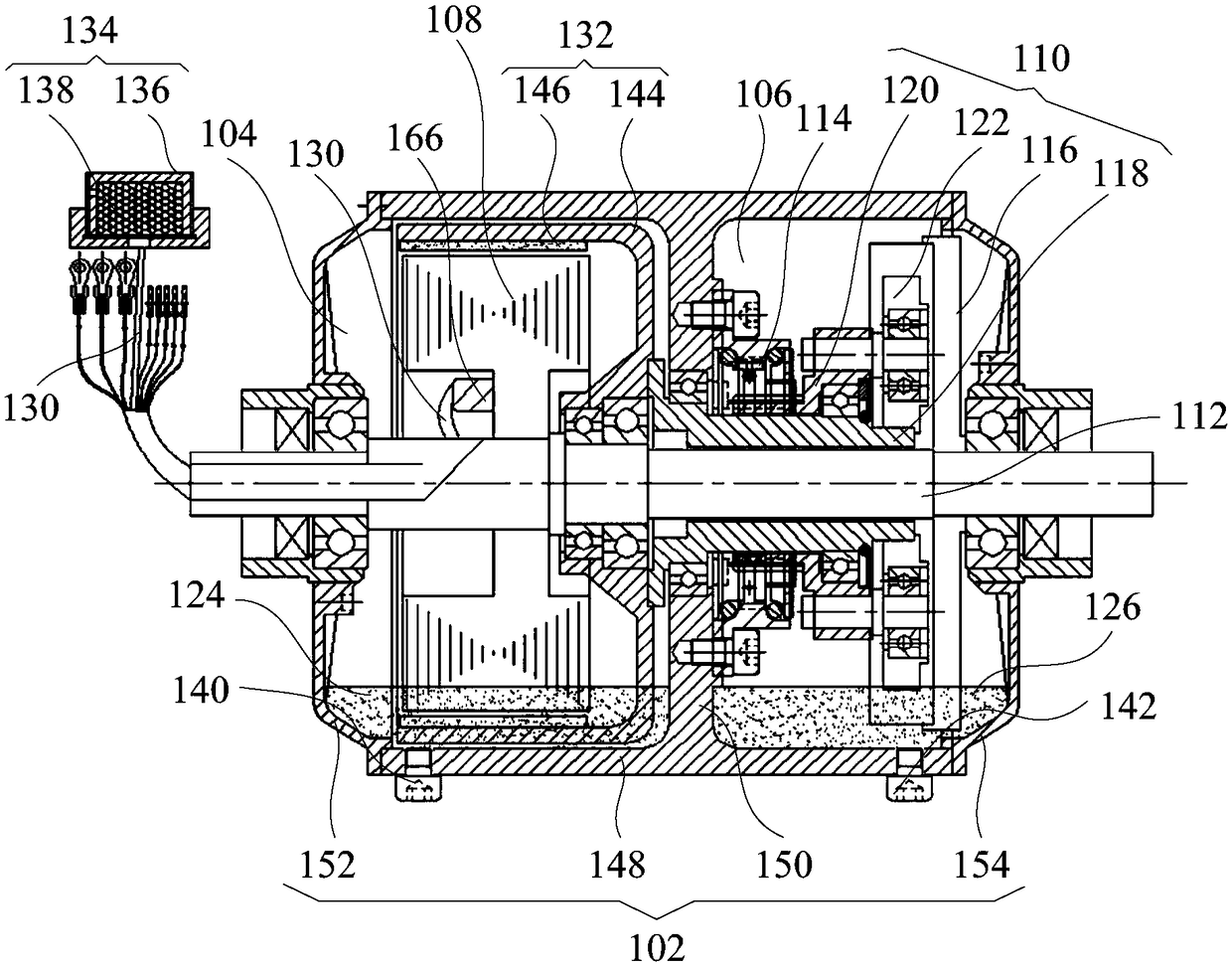
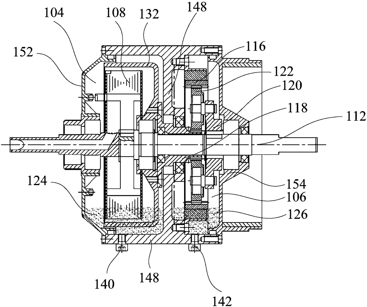
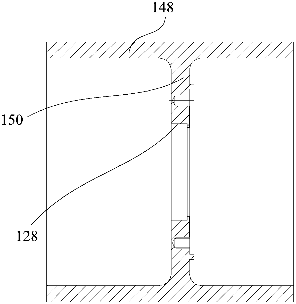
[0067] Refer below Figure 1 to Figure 6 A geared motor provided according to some embodiments of the present invention is described.

[0068] Such as Figure 1 to Figure 3 As shown, the geared motor p...


PUM


Abstract

The invention provides a gear motor. The gear motor comprises a shell, a motor shaft, a motor assembly and a gear reduction mechanism, wherein a first installation cavity, a second installation cavityand an installation hole for communicating the first installation cavity and the second installation cavity are arranged in the shell; the motor shaft is arranged in the installation hole in a sleeved mode, at least one end of the motor shaft extends out of the shell, and the motor shaft and the shell can rotate relative to each other; the motor assembly is arranged in the first installation cavity, the motor assembly comprises a stator winding assembly and a rotor assembly, wherein the stator winding assembly is fixed on a motor shaft, and the rotor assembly is arranged outside the stator winding assembly in a sleeved mode; the gear reduction mechanism is arranged in the second installation cavity, the input end of the gear reduction mechanism penetrates through the installation hole andis connected to the rotor assembly, and the output end of the gear reduction mechanism is connected to the shell. According to the technical scheme, the motor assembly and the gear reduction mechanism are not prone to influence each other, so that the accelerated aging of the gear reduction mechanism is not easily caused due to the fact that the temperature rise of the motor assembly is too high,and the situation that lubricating oil on the gear reduction mechanism intrudes into the motor assembly is avoided.

Description

technical field [0001] The invention relates to the field of motors, in particular to a geared motor. Background technique [0002] At present, in order to reduce the overall size of the existing deceleration motors on the market, the deceleration mechanism and the motor assembly are arranged in the same cabin. Due to the limited heat dissipation conditions of the motor assembly, the heat of the motor assembly cannot be dissipated quickly. There is a greater risk of burning. At the same time, the temperature rise of the motor assembly transmitted to the reduction mechanism will accelerate the aging speed of grease, lubricating oil and gears, resulting in the problems of easy lubrication failure, large transmission noise and high maintenance costs. In addition, since the deceleration mechanism and the motor assembly are in the same cabin, there is also the problem that lubricating oil can easily invade the motor assembly, resulting in electric leakage and easy damage to the ...

Claims


Application Information

Patent Timeline
Patent Type & Authority Applications(China)
IPC IPC(8): H02K7/116H02K7/108H02K9/19H02K5/10H02K5/15
CPCH02K7/116H02K5/10H02K5/15H02K7/108H02K9/19
Inventor 倪捷陈文胜吴启皇
Owner ZHEJIANG LUYUAN ELECTRIC VEHICLE
Why Eureka
Try Eureka