
Heat-dissipating structure of high-frequency direct-current X-ray generator

A heat dissipation structure and X-ray technology, applied in the direction of X-ray equipment, electrical components, etc., can solve the problems of poor heat dissipation effect and difficulty in eliminating static heat dissipation, so as to prevent shell deformation, improve heat dissipation effect, and improve heat dissipation efficiency Effect

Pending Publication Date: 2018-11-06
杭州惠威无损探伤设备有限公司
View PDF0 Cites 0 Cited by
  • Summary
  • Abstract
  • Description
  • Claims
  • Application Information

AI Technical Summary

Problems solved by technology

[0003] The existing high-frequency capacitor voltage doubler DC X-ray generator is suitable for the current digital ray imaging (DR) requirements. The 8-stage capacitor voltage doubler modules in the generator are connected in series and are insulated by SF6 gas. Due to the static electricity on the surface of the module and the device The heat dissipation requirements limit the size reduction of the whole machine, the overall heat dissipation effect is not good, and it is difficult to eliminate static electricity and heat dissipation. A module has more than 10 components, and there are hundreds of components in level 8. The more components, the greater the probability of damage. To this end, we propose a high-frequency DC X-ray generator cooling structure

Method used


Image

  • Heat-dissipating structure of high-frequency direct-current X-ray generator
  • Heat-dissipating structure of high-frequency direct-current X-ray generator
  • Heat-dissipating structure of high-frequency direct-current X-ray generator

Examples


Embodiment Construction

[0018] The following will clearly and completely describe the technical solutions in the embodiments of the present invention with reference to the accompanying drawings in the embodiments of the present invention. Obviously, the described embodiments are only some, not all, embodiments of the present invention. Based on the embodiments of the present invention, all other embodiments obtained by persons of ordinary skill in the art without making creative efforts belong to the protection scope of the present invention.

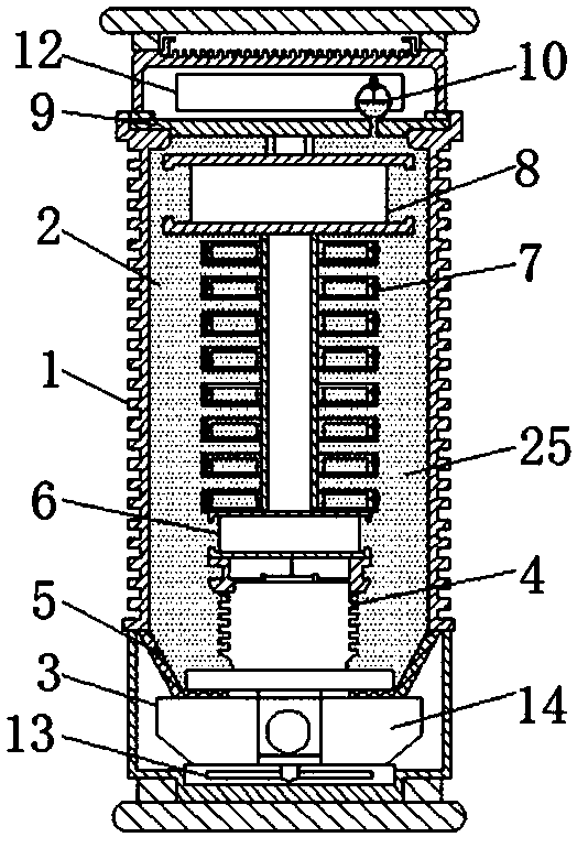
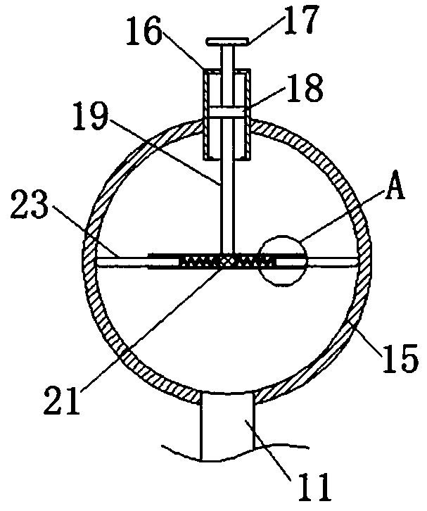
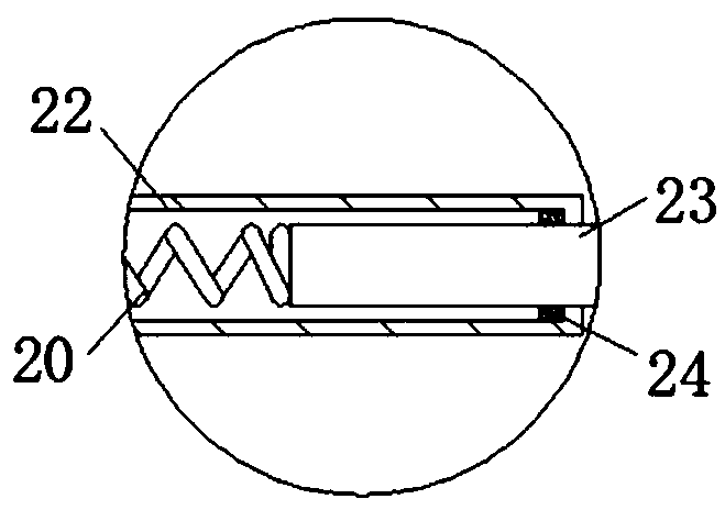
[0019] see Figure 1-4 , the present invention provides a technical solution: a high-frequency direct current X-ray generator heat dissipation structure, including a housing 1, a heat dissipation device 2 is fixedly connected inside the housing 1, and the heat dissipation device 2 includes a ventilator 3, a ceramic X-ray tube 4, isolation shell 5, filament voltage module 6, capacitor voltage doubler module 7, primary voltage module 8, baffle plate 9, spherical...


PUM


Abstract

The invention discloses a heat-dissipating structure of a high-frequency direct-current X-ray generator. The heat-dissipating structure comprises a shell, wherein a heat-dissipating device is fixedlyconnected into the shell; the heat-dissipating device comprises a ventilating component, a ceramic X-ray tube, an isolating shell, a filament voltage module, a capacitive voltage doubler module, a primary voltage module, a baffle plate, a spherical pressure buffering component, a connecting tube, a control circuit board and organosilicone oil; the ventilating component is fixedly connected to thebottom end of the inner part of the shell; the input end of the ventilating component is fixedly connected with the bottom of the ceramic X-ray tube; the isolating shell is fixedly connected to the bottom of the ceramic X-ray tube. Through reasonable layout of the modules immersed in the organosilicone oil, namely immersion of the modules in the organosilicone oil, the heat-dissipating efficiencyof the shell is improved, and thus the service life of a device is further prolonged.

Description

technical field [0001] The invention relates to the technical field of portable X-ray flaw detectors, in particular to a heat dissipation structure for a high-frequency DC X-ray generator. Background technique [0002] The early X-ray generators used transformer oil for insulation and heat dissipation. At that time, the high-voltage boost was in the power frequency (50HZ) AC mode, and the volume and weight were very large. Soon, SF6 gas insulation was adopted, and the high-voltage boost was medium-frequency pulse (200HZ). The direct current, instead of the early ray generator, uses SF6 gas insulation, and is cooled by a strong wind shell. The heat of the internal components can only be exchanged through the gas SF6 heat. The proportion of failures caused by overtemperature accounts for 1 / 3 of this type of ray generator. [0003] The existing high-frequency capacitor voltage doubler DC X-ray generator is suitable for the current digital ray imaging (DR) requirements. The 8-st...

Claims


Application Information

Patent Timeline
Patent Type & Authority Applications(China)
IPC IPC(8): H05G1/02
CPCH05G1/025
Inventor 汤立信郭伟蒋华洪周国鹏余永申杨宗兵何华徐孝雅
Owner 杭州惠威无损探伤设备有限公司
Learn More