Lashing bar numerical control hydraulic high-speed horizontal forging machine and using method thereof

A technology for binding rods and flat forging machines, which is applied to forging presses, forging presses, driving devices of forging presses, etc., can solve the problems of poor operating conditions and low processing efficiency, and achieves convenient operation, processing efficiency and output improvement. The effect of installation and removal

Pending Publication Date: 2018-11-09
NANJING AIMANDA SHIP EQUIP MFG
View PDF8 Cites 1 Cited by
  • Summary
  • Abstract
  • Description
  • Claims
  • Application Information

AI Technical Summary

Problems solved by technology

[0004] In this kind of flat forging machine with vertical die splitting, the die parting surface of the die is in a vertical position, and the die chambers of several die forging steps of a forging are arranged up and down in the vertical direction, so the operating conditions are poor and the processing efficiency is low.

Method used


Image

  • Lashing bar numerical control hydraulic high-speed horizontal forging machine and using method thereof
  • Lashing bar numerical control hydraulic high-speed horizontal forging machine and using method thereof
  • Lashing bar numerical control hydraulic high-speed horizontal forging machine and using method thereof

Examples


Embodiment Construction

[0029] Below in conjunction with accompanying drawing, technical scheme of the present invention is described in further detail:

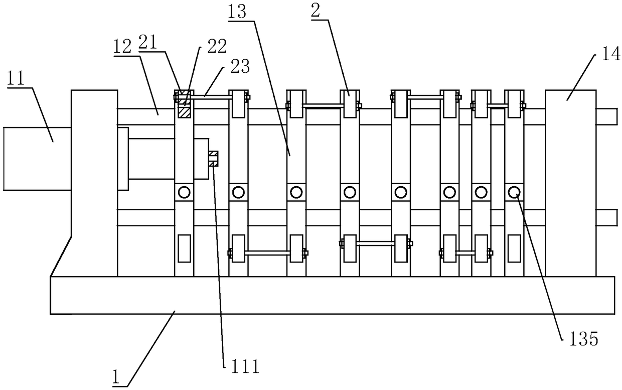
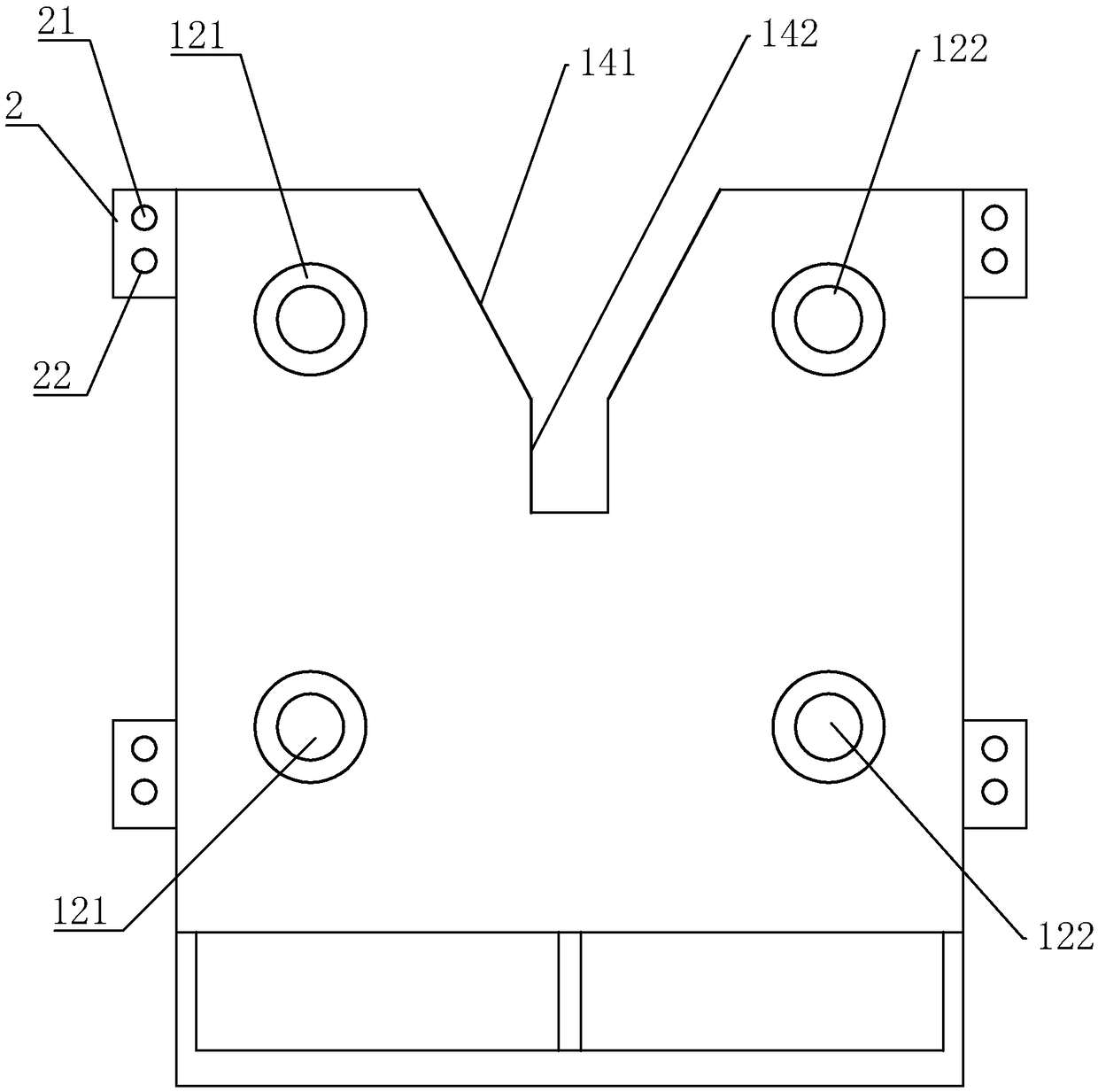
[0030] The present invention aims to provide a binding rod numerical control hydraulic high-speed flat forging machine, such as figure 1 As shown, it includes a base 1, and one end of the base 1 is provided with a horizontally placed main shaft hydraulic cylinder 11, and the main shaft hydraulic cylinder 11 is provided with guide rods 12 on both sides of its main shaft piston rod, and a mold body 13 is provided on the guide rod 12, The guide rod 12 is arranged coaxially with the main shaft piston rod, and the end of the base 1 away from the main shaft hydraulic cylinder 11 is provided with a support seat 14 for fixing the guide rod 12 .

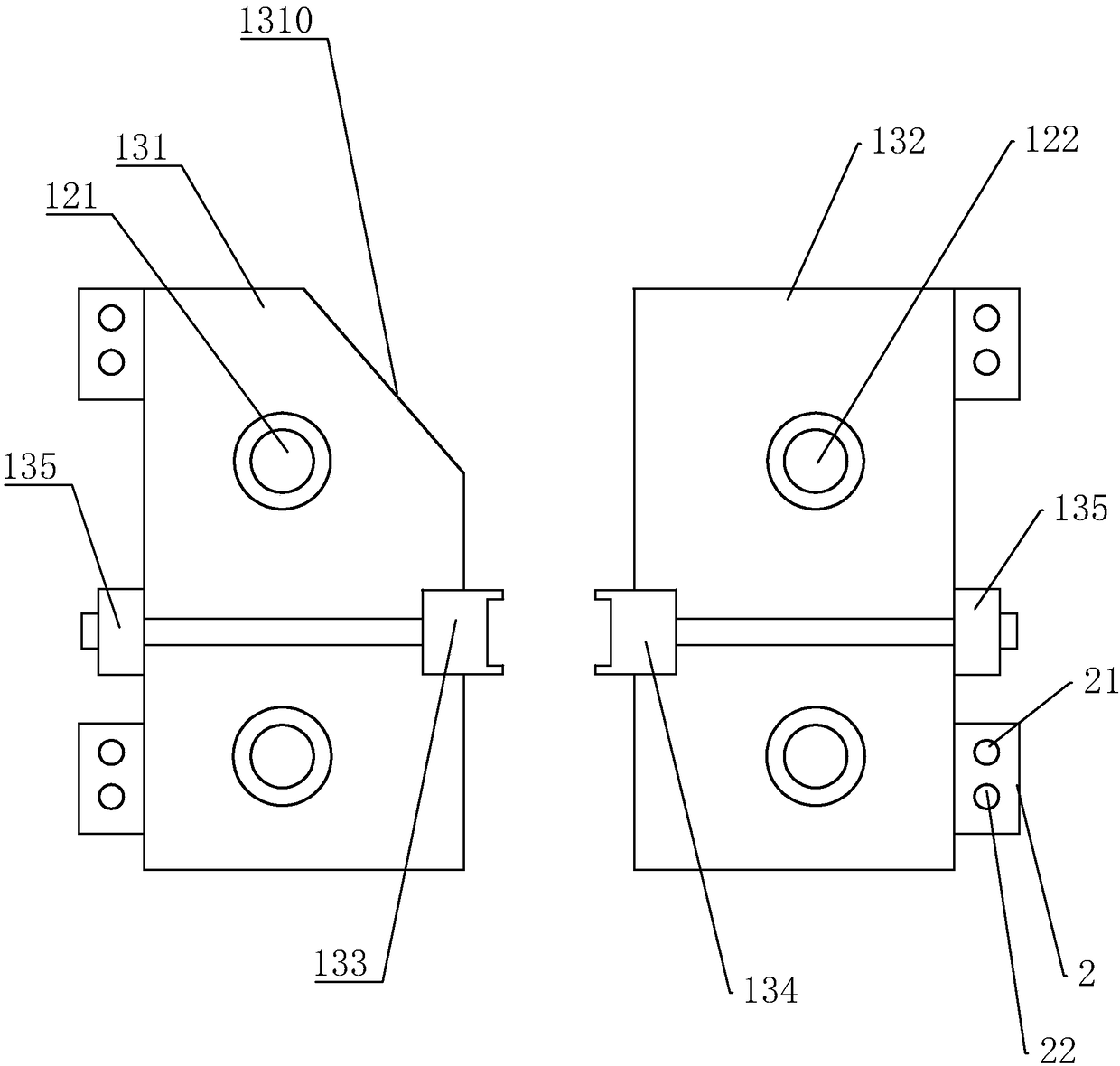
[0031] The guide rod 12 includes a pair of left guide rods 121 and a pair of right guide rods 122. The left guide rods 121 are jointly pierced with a number of left mold bodies 131, and the left mold body 131 is v...


PUM


Abstract

The invention discloses a lashing bar numerical control hydraulic high-speed horizontal forging machine and a using method thereof. The lashing bar numerical control hydraulic high-speed horizontal forging machine comprises a base, wherein a spindle hydraulic cylinder placed horizontally is arranged at one end of the base, and guiding rods are arranged on the positions, located on the two sides ofa spindle piston rod of the spindle hydraulic cylinder, of the spindle hydraulic cylinder; the guiding rods are provided with mold bodies, the guiding rods and the spindle piston rod are coaxially arranged, and a supporting seat for fixing the guiding rods is arranged at the end, far away from the spindle hydraulic cylinder, of the base; the guiding rods include a pair of left guiding rods and apair of right guiding rods, and a plurality of left mold bodies are jointly disposed on the left guiding rods in a penetrating mode; and left mold cavities are vertically formed in the positions, facing the axis of the spindle piston rod, in the left mold bodies, and the left mold cavities are connected with an auxiliary hydraulic cylinder to drive the left mold cavities to move towards or away from the axis of the spindle piston rod; and correspondingly, a plurality of right mold bodies corresponding to the left mold cavities one to one are jointly arranged on the right guiding rods in a penetrating mode, and the right mold bodies are provided with right mold cavities and are connected with the auxiliary hydraulic cylinder. The lashing bar numerical control hydraulic high-speed horizontalforging machine can realize multi-stage forging rough on workpieces, and the spacing of the adjacent forged rough portions can be adjusted according to actual requirements.

Description

technical field [0001] The invention relates to a flat forging machine, in particular to a numerically controlled hydraulic high-speed flat forging machine for binding rods and a method for using the same. Background technique [0002] Flat forging machine is also called horizontal forging machine. As a branch of mechanical press, flat forging machine mainly produces die forgings by local upsetting. In addition to local gathering steps, the equipment can also realize punching, bending, flanging, trimming and cutting. Due to its high productivity, it is suitable for mass production. Therefore, it is widely used in automobile, tractor, bearing and aviation industry. [0003] The Chinese patent with the notification number CN204524125U discloses a vertical split die four-station flat forging machine, including a frame on which a horizontally arranged longitudinal die device and a transverse die clamping device, a longitudinal die device and a transverse die clamping device a...

Claims


Application Information

Patent Timeline
Patent Type & Authority Applications(China)
IPC IPC(8): B21J9/08B21J9/12B21J13/02B21J13/04
CPCB21J9/08B21J9/12B21J13/02B21J13/04
Inventor 陈长明陈琦
Owner NANJING AIMANDA SHIP EQUIP MFG
Why Eureka
Try Eureka