Capillary tube apparatus and method for automatically measuring viscosity of refrigerating fluid and lubricating oil

An automatic measurement and refrigerant technology, applied in the direction of DC flow characteristics measurement, etc., can solve the problems of reducing the accuracy of the results, low stability, difficult automatic measurement, etc., to improve the accuracy and stability, avoid repeated charging, Achieve the effect of repeated measurements

Active Publication Date: 2018-11-09
TIANJIN UNIV
View PDF7 Cites 1 Cited by
  • Summary
  • Abstract
  • Description
  • Claims
  • Application Information

AI Technical Summary

Problems solved by technology

[0003] Currently commonly used capillary viscometers are suitable for different occasions and can measure the viscosity of various liquids, but they cannot automatically and accurately measure the viscosity of volatile mixed working fluids. The main problems are as follows: (1) At present, manual stopwatches are often used for capillary viscosity measurement , there is human error, which reduces the accuracy of the results, and it is difficult to realize automatic measurement (2) When measuring with a commonly used viscometer, the liquid to be tested is mostly in direct contact with the outside air. Using a capillary viscometer to measure in a sealed environment is currently a commonly used method in China, or the measurement accuracy is not high, or the stability is not high (3) The capillary viscometer has a narrow measurement range, and it is difficult for a single viscometer to measure several viscosities. large working medium

Method used


Image

  • Capillary tube apparatus and method for automatically measuring viscosity of refrigerating fluid and lubricating oil
  • Capillary tube apparatus and method for automatically measuring viscosity of refrigerating fluid and lubricating oil
  • Capillary tube apparatus and method for automatically measuring viscosity of refrigerating fluid and lubricating oil

Examples


Embodiment Construction

[0026] In order to have a clearer understanding of the technical features, purposes and effects of the method, the technical solution of the present invention will be further described below in conjunction with the accompanying drawings and specific implementation methods.

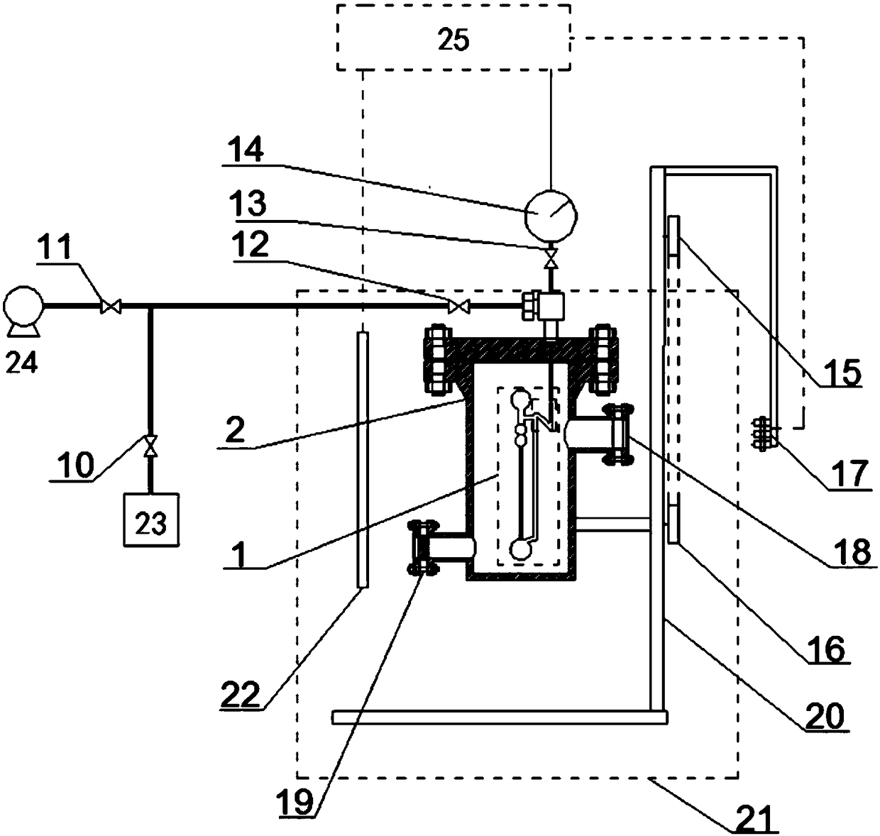
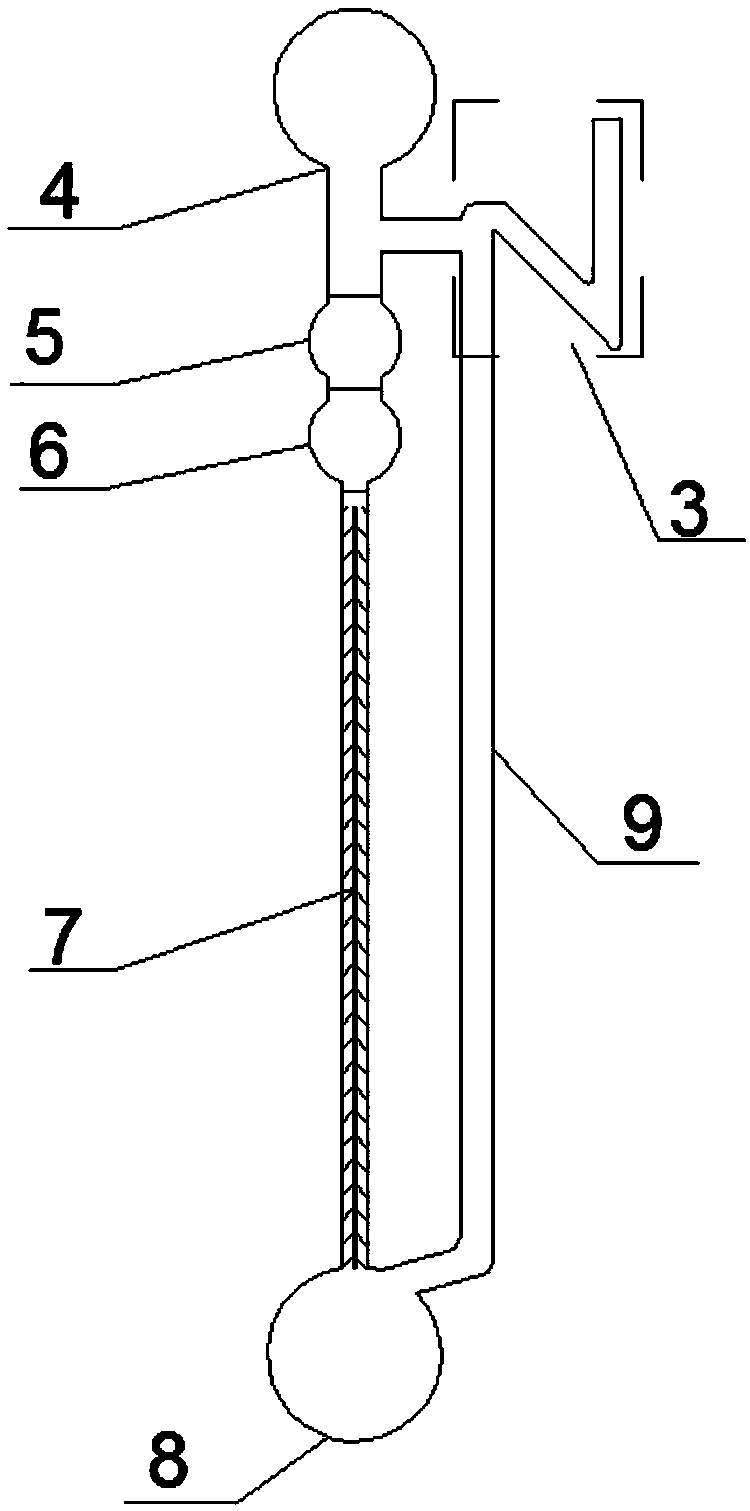
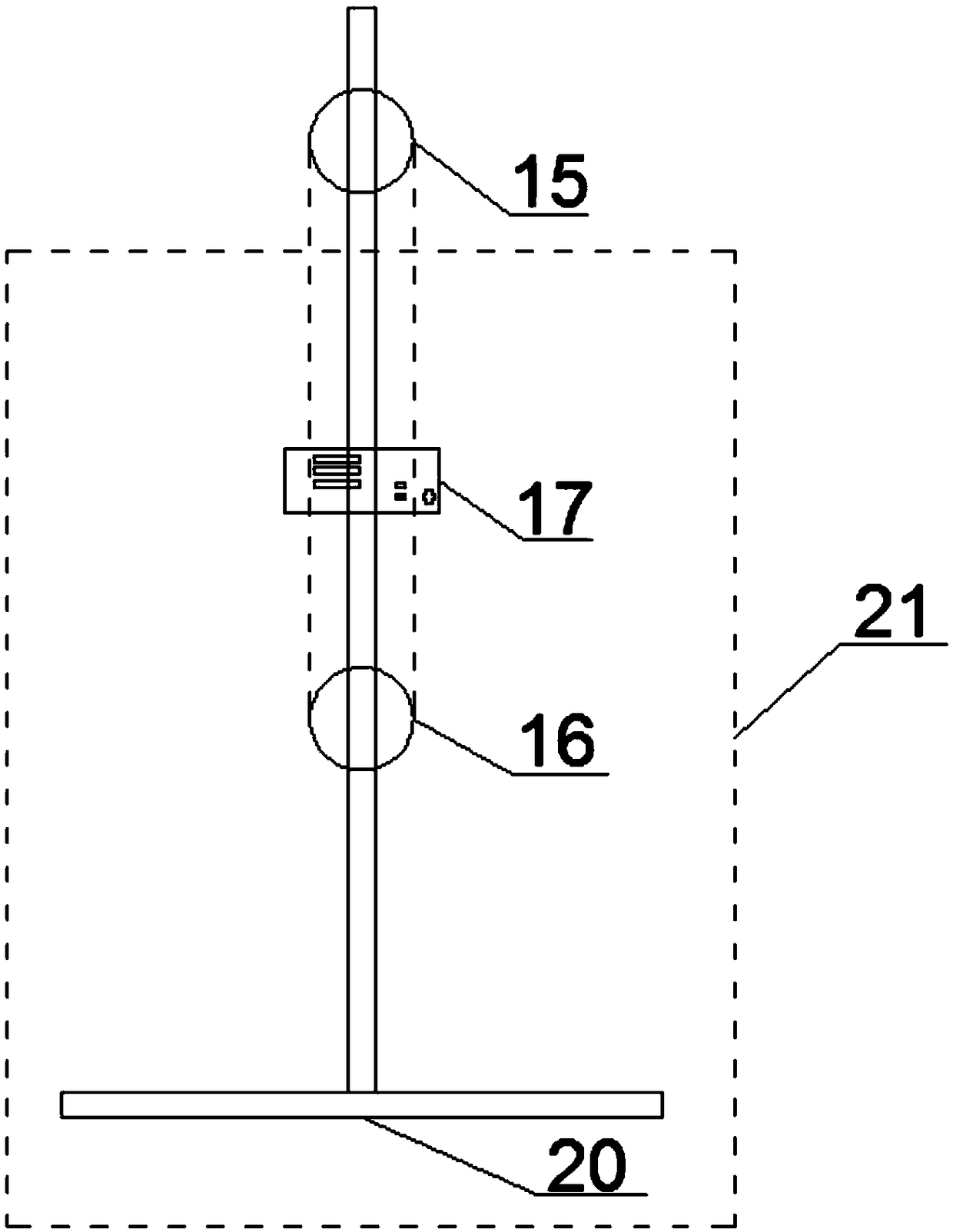
[0027] Such as Figure 1 to Figure 3 As shown, the present invention provides a capillary device for automatically measuring the viscosity of refrigerant and lubricating oil, which is arranged in a constant temperature tank 21, and the top of the pressure vessel 2 is connected with a vacuum pump 24 and a refrigerant tank 23 through a connecting pipe. The connection between the vacuum pumps 24 is controlled by the main valve 12 and the second valve 11, the connection between the pressure vessel 2 and the refrigerant tank 23 is controlled by the main valve 12 and the first valve 10, and the connection between the pressure vessel 2 and the pressure sensor 14 is controlled by The third valve 13 controls. The ...


PUM


Abstract

The invention discloses a capillary tube apparatus and method for automatically measuring the viscosity of refrigerating fluid and lubricating oil. The capillary tube apparatus is composed of a fixingbracket, a laser sensor, a rotary transmission mechanism and a pressure vessel, wherein a capillary tube viscometer is fixedly arranged inside the pressure vessel and is composed of an upper liquid reservoir, an upper timing ball, a lower timing ball, a capillary tube, a lower liquid reservoir, a by-pass pipe and an N-shaped pipe; the upper liquid reservoir, the upper timing ball, the lower timing ball, the capillary tube and the lower liquid reservoir are communicated with one another in sequence from top to bottom; the upper liquid reservoir and the lower liquid reservoir are connected witheach other by virtue of the by-pass pipe; the volumes of the upper liquid reservoir and the lower liquid reservoir are the same and are larger than volumes of the upper timing ball and the lower timing ball; and the N-shaped pipe is arranged at the upper end of the by-pass pipe and is used for realizing two functions of injecting liquid and preventing turning and liquid leaking. With the adoptionof the design of the N-shaped pipe, the liquid can be conveniently injected, the liquid can be prevented from leaking into the pressure vessel via the liquid injection port in the process of turningto ascending feed, and to-be-measured liquid is prevented from being repeatedly filled.

Description

technical field [0001] The invention belongs to the field of liquid viscosity testing, in particular to a capillary device and method for measuring the viscosity of refrigerant and lubricating oil in a high-pressure environment. Background technique [0002] A viscometer is an instrument used to measure the viscosity of fluids (liquids and gases). Viscosity is one of the basic physical parameters of fluids, and the acquisition of viscosity parameters plays a vital role in the development of many industries. Therefore, more and more attention has been paid to the measurement and research of viscosity. Viscometers are mainly divided into three categories: capillary viscometer, rotational viscometer and falling ball viscometer. Capillary viscometers are widely used because of their simplicity, reliability, and high accuracy, and are suitable for occasions with special requirements, occupying a large market in the domestic viscosity measurement field. [0003] Currently commo...

Claims


Application Information

Patent Timeline
Patent Type & Authority Applications(China)
IPC IPC(8): G01N11/06
CPCG01N11/06Y02B30/70
Inventor 杨昭陈裕博翟瑞冯彪吕子建赵文仲余飞冯蕊
Owner TIANJIN UNIV
Why Eureka
Try Eureka