DC voltage switch

A technology of DC voltage switch and DC grid, applied in the direction of electric switch, electronic switch, high voltage/high current switch, etc., can solve the problem of limited life of voltage limiting components, etc., and achieve the effect of realizing components, reliable suppression or extinguishing

Inactive Publication Date: 2018-11-09
SIEMENS AG
View PDF7 Cites 3 Cited by
  • Summary
  • Abstract
  • Description
  • Claims
  • Application Information

AI Technical Summary

Problems solved by technology

But the pressure limiting element has a limited lifetime

Method used


Image

  • DC voltage switch
  • DC voltage switch

Examples


Embodiment Construction

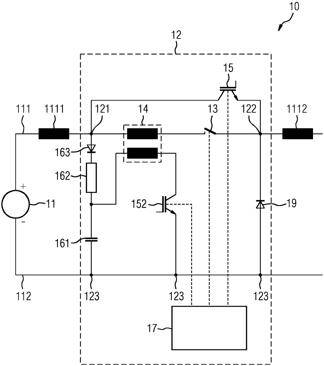
[0023] figure 1 A direct voltage switch 12 in a part of a direct current grid 10 is shown as an exemplary embodiment of the invention. The DC grid 10 is powered by a DC voltage source 11 , thus supplying the DC grid 10 with a DC voltage. DC grid 10 can be A network in a power supply or, for example, a network in a vehicle, such as a locomotive or a motor vehicle, or a network in the field of supplying a network of electric vehicles. In principle, this principle applies to all voltage classes from low to medium to high voltage. The DC voltage switch 12 is arranged between a load not shown and the DC voltage source 11 . In this case, the DC voltage switch 12 is connected in series via first and second connection terminals 121 , 122 into the first pole 111 of the DC network 10 . The third connection terminal 123 is connected to the second pole of the DC grid 10 .

[0024] Between the first and second connection terminals 121 , 122 , the DC voltage switch 12 has a series cir...


PUM


Abstract

The invention relates to a DC voltage switch having a first and second terminal for serial incorporation in a first pole of a DC voltage network, wherein a secondary current path having a semiconductor switch extends between the terminals, and an operating current path having a mechanical switch and, in series therewith, the primary-side winding of a transformer is arranged in parallel with the secondary current path, the secondary-side winding of the transformer is wired between a voltage source and a third terminal for incorporation into a second pole of the DC voltage network, a switch in series with the secondary-side winding of the transformer is arranged between the voltage source and the third terminal, the voltage source is connected to the first terminal via a diode and a chargingresistor, there is a control device for driving the switch, which is configured to determine the voltage of the voltage source repeatedly after the mechanical switch has been opened and to switch theswitch on at intervals in such a way that the voltage determined remains below a definable threshold value.

Description

technical field [0001] The invention relates to a DC voltage switch having two terminals, between which an operating current path with a mechanical switch and a bypass current path with a semiconductor switch running in parallel therewith run. Background technique [0002] Breaking direct current (DC current) is more difficult than breaking alternating current (AC current) since there is no zero crossing point. In the case of AC currents, the arc formed when opening the contacts is extinguished at the next current zero crossing in a suitable design, while in the case of DC currents, the arc continues to burn over a greater distance until the switch is damaged . [0003] Different designs are known to achieve a reliable disconnection of the DC current. One such design is based on generating a reverse current that compensates the load current such that the current in the mechanical switch achieves a zero crossing. The switch can then be opened without current flow, so that ...

Claims


Application Information

Patent Timeline
Patent Type & Authority Applications(China)
IPC IPC(8): H03K17/16H01H9/54H01H33/59
CPCH01H9/542H03K17/16H01H33/596
Inventor J.鲁普
Owner SIEMENS AG
Why Eureka
Try Eureka