Supercharge Your Innovation With Domain-Expert AI Agents!

Quick positioning cutting device for automobile data recorder processing

A driving recorder and cutting device technology, applied in the field of cutting devices, can solve problems such as affecting production efficiency, wasting resources, wasting human resources, etc., and achieving the effects of facilitating work tools and testing tools, avoiding safety accidents, and reducing production costs

Inactive Publication Date: 2018-11-13
芜湖凯兴汽车电子有限公司
View PDF11 Cites 0 Cited by
  • Summary
  • Abstract
  • Description
  • Claims
  • Application Information

AI Technical Summary

Problems solved by technology

[0004] The purpose of the present invention is to provide a cutting device that can be quickly positioned for the processing of driving recorder, so as to solve the problem that the positioning device that can be positioned quickly is not provided in the above-mentioned background technology, so that the user needs to manually calibrate and clamp during processing, which affects the Production efficiency, there is no water tank with water storage function, resulting in the liquid of the cutting workpiece being discharged directly without treatment, thereby polluting the environment and wasting resources, and there is no conveyor belt with automatic feeding function, resulting in users needing to follow the machining to carry materials all the time , a waste of human resources, affecting labor efficiency, without a shelf, it is inconvenient for users to place working tools and testing tools, and it is prone to safety accidents caused by littering

Method used


Image

  • Quick positioning cutting device for automobile data recorder processing
  • Quick positioning cutting device for automobile data recorder processing
  • Quick positioning cutting device for automobile data recorder processing

Examples


Embodiment Construction

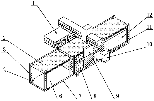
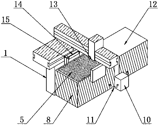
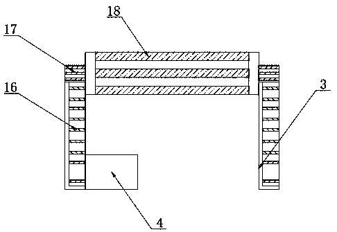
[0023] see Figure 1~4 , in an embodiment of the present invention, a cutting device that can be quickly positioned for processing a driving recorder includes a water cutter 1, a water tank 8 is installed under the front end of the water cutter 1, and a high-pressure water tank 12 is arranged on the right side of the water tank 8. And the left side of water tank 8 is provided with storage board 6, and water tank 8, storage board 6 and high-pressure water tank 12 are all installed on the base 7, and the top of water tank 8 and high-pressure water tank 12 is respectively provided with conveyor belt 2, and the upper end surface of base 7 is welded Conveyor belt bracket 3 is arranged, conveyor belt 2 and base 7 are connected to each other through conveyor belt bracket 3, positioning device 9 is arranged at the front and rear ends of water tank 8, water pump 10 is installed under the front end of water tank 8, water tank 8, high pressure water tank 12 and water pump 10 A plastic tu...


PUM


Abstract

The invention discloses a quick positioning cutting device for automobile data recorder processing. The quick positioning cutting device comprises a water cutting machine. A water tank is mounted below the front end of the water cutting machine. A high-pressure water tank is arranged on the right side of the water tank. Carrying plates are arranged on the left side of the water tank. Conveyor belts are arranged above the water tank and the high-pressure water tank correspondingly. Conveyor belt supports are welded to the surface of the upper end of a base. The conveyor belts and the base are connected through the conveyor belt supports. The front and rear ends of the water tank are both provided with positioning devices. A water pump is mounted on the lower portion of the front end of thewater tank. The quick positioning cutting device is provided with the positioning devices capable of conducting quick positioning, so that materials are quickly positioned and clamped through the positioning devices in the feeding process. The quick positioning cutting device is provided with the water tank with the water storage function for secondary utilization. Processing fluid is cyclically utilized. The production cost is lowered. The quick positioning cutting device is provided with the conveyor belts with the automatic feeding function. The three conveyor belts are used in cooperationwith the positioning devices, and the labor force is liberated.

Description

technical field [0001] The invention relates to the technical field of cutting devices, in particular to a fast-positioning cutting device for processing driving recorders. Background technique [0002] Waterjet cutting machines are superior to other processing technologies, such as flame cutting, plasma processing, laser processing, EDM, turning and milling, etc. At the same time, water cutting will not produce harmful gas or liquid, and will not generate heat on the surface of the workpiece. It is a real multi-functional, high-efficiency, cold cutting processing, positioning device, used to determine the required position of the workpiece or processing tool installation. [0003] However, the existing cutting device is not equipped with a positioning device that can be positioned quickly, causing the user to manually calibrate the clamping during processing, which affects production efficiency. Emissions, thereby polluting the environment and wasting resources. There is ...

Claims


Application Information

Patent Timeline
IPC IPC(8): B23D79/00
CPCB23D79/00
Inventor 刘健
Owner 芜湖凯兴汽车电子有限公司
Features
  • R&D
  • Intellectual Property
  • Life Sciences
  • Materials
  • Tech Scout
  • Unparalleled Data Quality
  • Higher Quality Content
  • 60% Fewer Hallucinations
Learn More