
Stamping machine

A hot stamping machine and hot stamping roller technology, which is applied in the field of hot stamping machines, can solve the problems of no hot stamping paper, fast heat loss of hot stamping rollers, and low temperature

Active Publication Date: 2018-11-13
SHAOXING XINHANG TEXTILE CO LTD
View PDF9 Cites 0 Cited by
  • Summary
  • Abstract
  • Description
  • Claims
  • Application Information

AI Technical Summary

Problems solved by technology

[0003] During hot stamping, there may be situations where the graphics and text are blurred, exposed or not hot stamped at all. The main reasons are: the temperature during hot stamping is too low, and the hot stamping temperature of the printing plate is too low to reach the electrochemical aluminum foil from the base and The minimum temperature required for transfer to the substrate. During hot stamping, the hot stamping paper is not completely transferred, resulting in blurred graphics, exposed bottoms, or hot stamping failure
[0004] When the existing hot stamping machine is hot stamping, the hot stamping rollers are exposed to the air, and the heat emitted by it is easy to dissipate
Especially in winter, the temperature difference between the air and the bronzing roller is large, and the heat loss of the bronzing roller is faster, resulting in a relatively unstable temperature of the bronzing roller, and it is easy to appear the phenomenon of too low temperature, which increases the occurrence of graphics and texts. The probability of exposed bottom or hot stamping failure will affect the quality of hot stamping

Method used

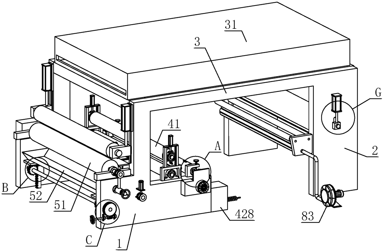

Image

  • Stamping machine
  • Stamping machine
  • Stamping machine

Examples


Embodiment Construction

[0049] The present invention will be described in detail below in conjunction with the accompanying drawings and embodiments.

[0050] A hot stamping machine, refer to figure 1 , including the first frame 1 and the second frame 2 placed on the ground, the end of the first frame 1 and the second frame 2 away from the ground is integrally formed with a third frame 3, and the first frame 1 is set There are cloth feeding device and gluing device, the second frame 2 is provided with a hot stamping device, and the third frame 3 is provided with an oven 31, the cloth feeding device, gluing device, oven 31 and hot stamping device are in accordance with The conveying direction is set sequentially.

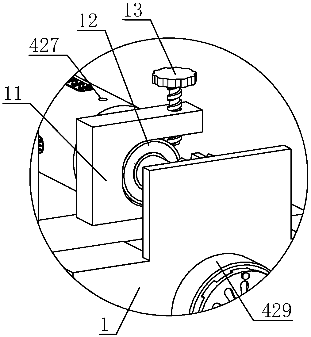
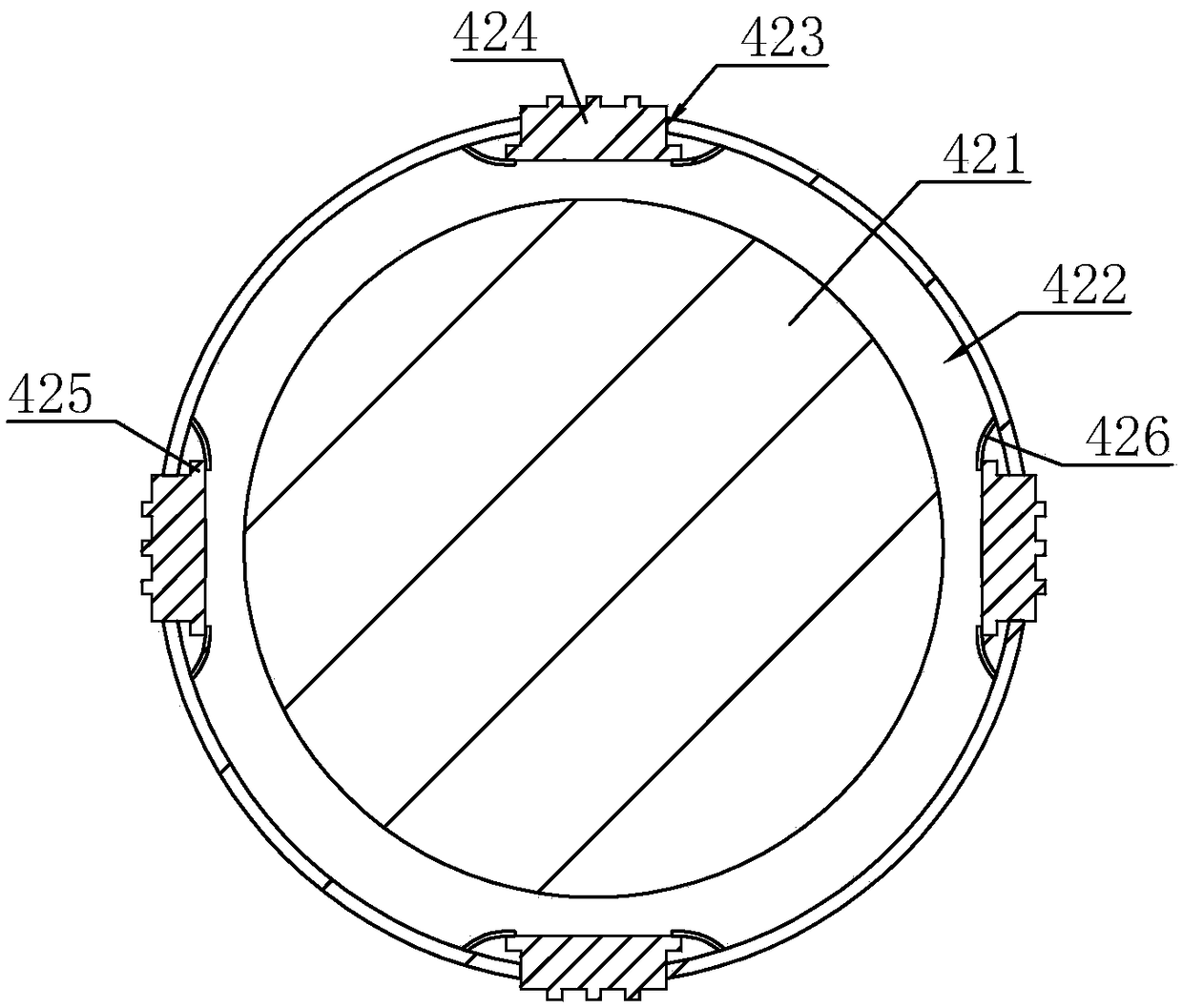
[0051] Reference 2 and image 3 , the cloth feeding device includes guide rollers 41 (see figure 1) and load rollers. A fixed frame 11 is fixedly installed on the first frame 1, and a groove is provided on one side of the fixed frame 11, and a first bearing 12 is slidably arranged in th...


PUM


Abstract

The invention discloses a stamping machine and relates to the technical field of printing and stamping equipment. The stamping machine comprises a second rack; a hot-stamping device is arranged on thesecond rack and comprises an abutting roller and a hot-stamping roller which are rotationally installed on the second rack; printing stock and alumite are clamped through the hot-stamping roller andthe abutting roller; the second rack is provided with an incubator, the hot-stamping roller is arranged in the incubator, and the incubator is provided with an inlet and an outlet; and a connection hole is formed in the side, facing the abutting roller, of the incubator, and the hot-stamping roller and the abutting roller press the alumite and the printing stock entering the incubator through theconnection hole. Through arrangement of the incubator, direct convection with air is avoided, the temperature of air surrounding the hot-stamping roller is increased, temperature difference between the hot-stamping roller and the surrounding air is reduced, heat dissipation of the hot-stamping roller is reduced accordingly, the probability of image and text floating or base exposure or hot-stamping failure is reduced, and thus the hot-stamping quality is improved.

Description

technical field [0001] The invention relates to the technical field of printing hot stamping equipment, more specifically, it relates to a hot stamping machine. Background technique [0002] The bronzing printing process uses hot pressing to transfer anodized aluminum, and transfers the aluminum layer in anodized aluminum to the surface of the substrate, so that a corresponding metal pattern appears on the surface of the substrate. [0003] During hot stamping, there may be situations where the graphics and text are blurred, exposed or not hot stamped at all. The main reasons are: the temperature during hot stamping is too low, and the hot stamping temperature of the printing plate is too low to reach the electrochemical aluminum foil from the base and The minimum temperature required for transfer to the substrate. During hot stamping, the hot stamping paper is not completely transferred, resulting in blurred graphics, exposed bottoms, or hot stamping failure. [0004] When...

Claims


Application Information

Patent Timeline
IPC IPC(8): B41F19/06B41F23/04
CPCB41F19/062B41F23/0483
Inventor 潘国海潘雨青潘彦玗
Owner SHAOXING XINHANG TEXTILE CO LTD
Learn More