
Noncontact yarn tension detection system and method

A yarn tension, non-contact technology, applied in the field of engineering and technical science, can solve the problems of long integration time of area array CCD, influence on measurement accuracy, high processing difficulty, etc., and achieve low measurement environment requirements, fast spinning speed, high The effect of precision

Pending Publication Date: 2018-11-13
FOSHAN UNIVERSITY
View PDF2 Cites 10 Cited by
  • Summary
  • Abstract
  • Description
  • Claims
  • Application Information

AI Technical Summary

Problems solved by technology

The non-contact measurement method based on the image of the yarn balloon proposed above is limited to measuring the yarn tension of the yarn during the winding process, which limits its application to a certain extent
[0007] However, the current technology is how to improve the measurement accuracy of the yarn tension detection system, and the measurement accuracy will be greatly reduced when the yarn with a smaller diameter is measured by the non-contact measurement method of obtaining the image of the yarn balloon; CCD It is an integrating device, which samples the measured original signal by means of integration. The area array CCD has a relatively long integration time and is difficult to process.
will eventually affect the measurement accuracy

Method used


Image

  • Noncontact yarn tension detection system and method
  • Noncontact yarn tension detection system and method

Examples


Embodiment Construction

[0036] The present invention will be further described below in conjunction with specific embodiments. The exemplary embodiments and descriptions of the present invention are used to explain the present invention, but not as a limitation to the present invention.

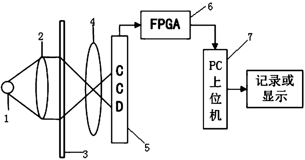
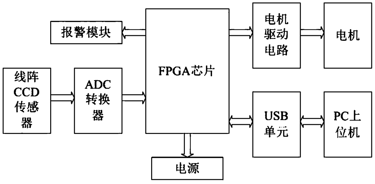
[0037] Such as figure 1 , figure 2 As shown, a non-contact yarn tension detection system of this embodiment includes a yarn guide wheel (not shown in the figure) for conducting the yarn 3, the yarn guide wheel is driven by a motor, and also includes a linear array CCD The detection head that image acquisition device forms, FPGA chip 6, the power supply that is used to supply power for FPGA chip 6, PC upper computer 7, described linear array CCD image acquisition device comprises parallel light source 1, is positioned at the passing path of parallel light source 1 successively Prism 2, imaging lens 4 and linear array CCD sensor 5, described yarn 3 passes the gap between prism 2 and imaging lens 4 and yarn 3 is para...


PUM


Abstract

The invention discloses a noncontact yarn tension detection system and method. The system comprises a yarn guiding wheel, a detection head, an FPGA chip, a power supply and a PC upper computer, wherein the yarn guiding wheel is used for conveying yarns, the detection head is formed by a linear array CCD image collection device, and the power supply is used for supplying power to the FPGA chip; andthe linear array CCD image collection device comprises a parallel light source, a prism, an imaging lens and a linear array CCD sensor, wherein the prism, the imaging lens and the linear array CCD sensor are sequentially located on a passing route of the parallel light source, a shade of the yarn is imaged on the linear array CCD sensor under the irradiation of the parallel light source, the linear array CCD sensor is used for detecting the size change of the shade of the yarn and transmitting a size change signal of the shade into an ADC converter, and the ADC converter is used for converting a received analog signal into a digital signal, transmitting the digital signal into the FPGA chip and calculating a tension value of the yarn. According to the noncontact yarn tension detection system, the tension value of the yarn can be measured in a noncontact manner in the continuous working process of a spinning frame, and compared with an existing contact yarn measurement manner, the precision is relatively high.

Description

technical field [0001] The invention relates to the fields of engineering and technical sciences, in particular to a non-contact yarn tension detection system and method. Background technique [0002] China is a big textile country and has an irreplaceable position in the textile field. At the same time, people have higher and higher requirements for the quality of textiles used in daily life. In the textile processing process, the tension of the yarn is a very important parameter. The size and stability of the tension are directly related to the quality, grade, production efficiency and smooth progress of subsequent processing of the product. [0003] For a long time, yarn tension control has been one of the difficult problems in the spinning industry. The difficulties come from two aspects: one is that the value of yarn tension is so small that it is difficult to measure and control; the other is that the cost of yarn tension control is too high . [0004] At present, th...

Claims


Application Information

Patent Timeline
Patent Type & Authority Applications(China)
IPC IPC(8): D01H13/10D01H13/32D01H13/16
CPCD01H13/10D01H13/165D01H13/32
Inventor 徐伟聪谢嘉宁黄世銮马智健
Owner FOSHAN UNIVERSITY
Learn More