Concrete pumping movable arm and concrete spreader comprising same

A technology for concrete pumps and movable arms, which is applied in earthwork drilling, wellbore lining, tunnel lining, etc. It can solve the problems of wasting sites, pollution, heavy workload and labor intensity, and meet the needs of expansion and contraction. The overall structure is simplified and convenient. The effect of production

Pending Publication Date: 2018-11-13
HUNAN WUXIN TUNNEL INTELLIGENT EQUIP CO LTD
View PDF5 Cites 0 Cited by
  • Summary
  • Abstract
  • Description
  • Claims
  • Application Information

AI Technical Summary

Problems solved by technology

[0003] This method has the following defects: (1) the pumping interface needs to be frequently replaced during construction, and the pipe needs to be dismantled, replaced, cleaned, connected, and fixed each time the interface is replaced. The workload and labor intensity are large and time-consuming; ( 2) The pumping of concrete needs to be stopped during the dismantling of the pipe, because the slump loss of the concrete remaining in the pump pipe due to the long pause time can easily cause the pipe to be blocked; The concrete is easy to form cold joints, which affects the quality of pouring; (4) Frequent replacement of the pumping interface will leave and overflow some concrete in the pipe, resulting in waste and on-site pollution; Operation, higher position may cause safety accidents

Method used


Image

  • Concrete pumping movable arm and concrete spreader comprising same
  • Concrete pumping movable arm and concrete spreader comprising same
  • Concrete pumping movable arm and concrete spreader comprising same

Examples


Embodiment 1

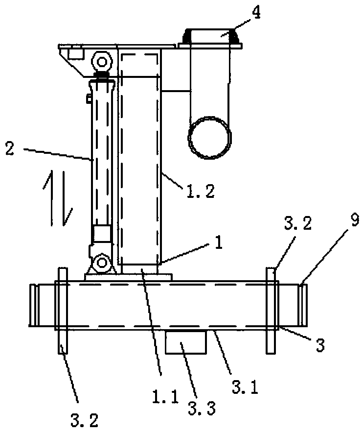
[0030] see figure 1 ( figure 1 Middle: the telescopic mechanism is in the retracted state, and the bidirectional arrow is the telescopic direction of the telescopic mechanism), a movable arm for concrete pumping, including a movable arm 1, a telescopic control part 2 that drives the movable arm 1 to perform telescopic movement, and drives the movable arm 1. A rotation control part 3 for rotating the movable arm 1 .

[0031] The movable arm 1 includes a guide post 1.1 and a guide sleeve 1.2, the lower end of the guide post 1.1 is fixed on the rotation control part 3, and the lower end of the guide sleeve 1.2 is sleeved on the upper end of the guide post 1.1 , and the concrete output end 4 is fixed on the guide sleeve 1.2.

[0032] The telescopic control part 2 includes a group of telescopic mechanisms (at least two groups of telescopic mechanisms arranged side by side can also be used according to the actual situation), and the telescopic mechanisms are telescopic along the c...

Embodiment 2

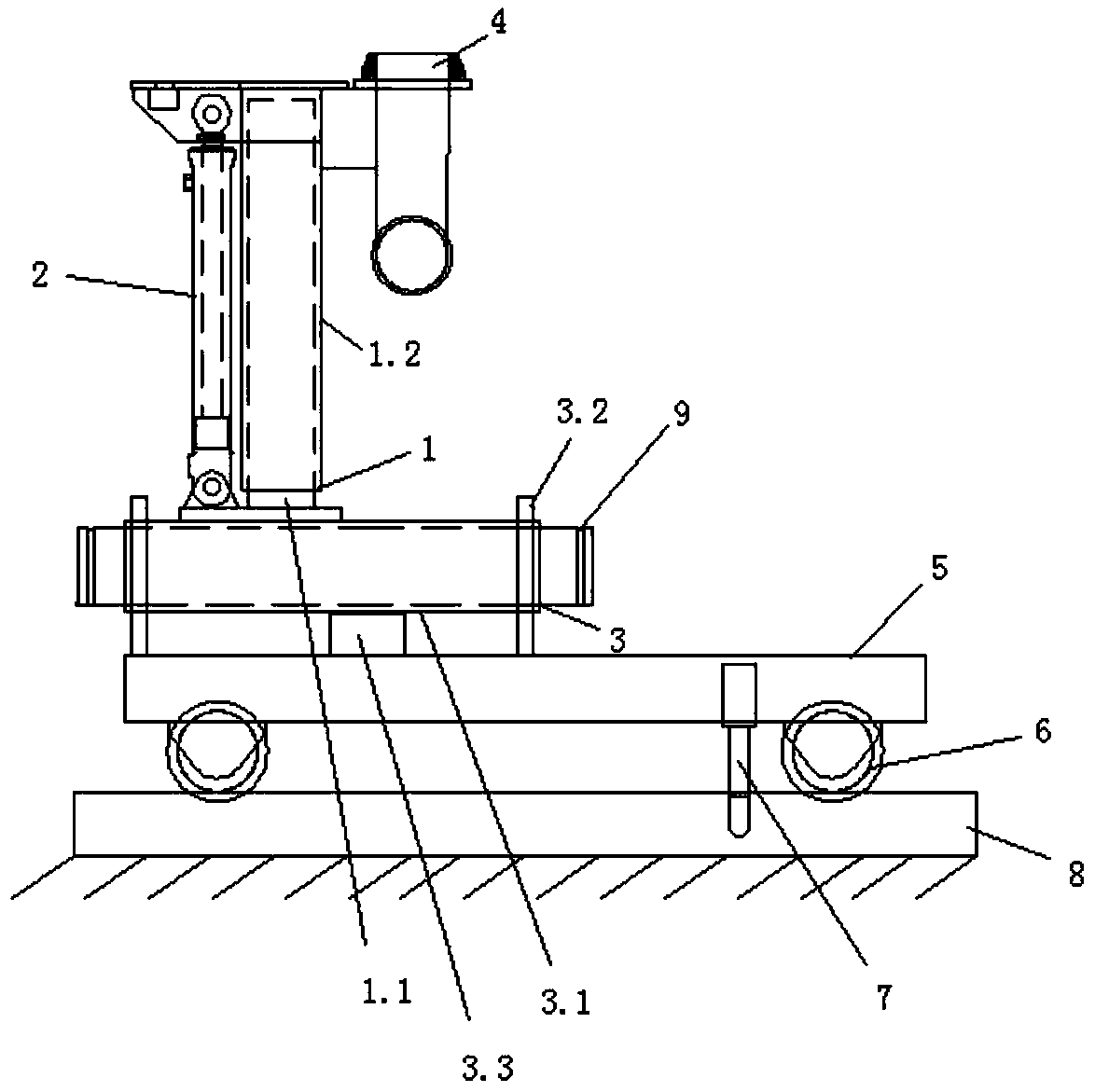
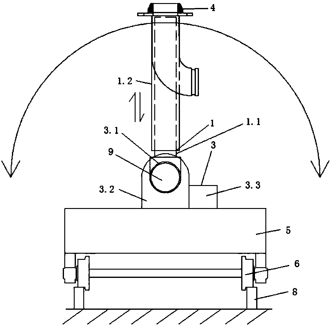
[0038] see figure 2 with image 3 ( image 3Middle: The arc arrow indicates the swing direction of the movable arm, and the straight double arrow indicates the telescopic direction of the telescopic mechanism; figure 2 with image 3 Middle: the telescopic mechanism is in the retracted state), a concrete placing machine, the detailed structure is: including the car body 5, the traveling mechanism 6, the locking mechanism 7, the concrete pumping movable arm as described in Embodiment 1, and the concrete pumping arm connected to the concrete The pipeline (not shown) of the output end 4 and the concrete pumping mechanism and the console (not shown).

[0039] The support base 3.2 is arranged on the upper surface of the car body 5, and it includes two sets of support bodies arranged side by side. The end is the point of force, which can realize rotation along its central axis.

[0040] The running gear 6 matches the running track 8 (the running track 8 here can be arranged on...


PUM


Abstract

The invention provides a concrete pumping movable arm. The concrete pumping movable arm comprises a movable arm, a telescopic control part which drives the movable arm to perform telescopic movement and a rotary control part which drives the movable arm to rotate. The concrete pumping movable arm is applied, the concrete pumping movable arm has the effects that the whole structure is tidy, the combined design of the telescopic control part, a rotary control part and the movable arm is adopted to realize the concrete pumping output at different positions in the plane through the rotary swing and telescopic of the movable arm, and the practicability is high. The invention further provides a concrete spreader. The concrete spreader comprises a vehicle body, a travelling mechanism, a locking mechanism, the concrete pumping movable arm and a pipeline. The travelling mechanism is matched with a travelling track arranged on the lining trolley and arranged on the lower surface of the vehicle body. The locking mechanism is movably arranged on the vehicle body. The concrete spreader is applied, the concrete pumping output at different positions in the plane can be realized through the rotaryswing and telescopic of the movable arm, and the construction efficiency is high.

Description

technical field [0001] The invention relates to the technical field of lining, in particular to a concrete pumping movable arm and a concrete distributing machine including the movable arm. Background technique [0002] During the concrete construction of the second lining of the tunnel, it is necessary to pump the concrete into the cavity between the formwork and the excavation surface through different positions on the formwork to complete the pouring. At present, when it is necessary to replace the concrete pumping interface, it is necessary to manually remove the clamp and the pumping tube on the pumping tube, replace the pumping tube with a suitable length and adjust the position of the pipeline outlet, and then reconnect with the next pumping interface before installing. [0003] This method has the following defects: (1) the pumping interface needs to be frequently replaced during construction, and the pipe needs to be dismantled, replaced, cleaned, connected, and fix...

Claims


Application Information

Patent Timeline
Patent Type & Authority Applications(China)
IPC IPC(8): E21D11/10
CPCE21D11/105
Inventor 曾勇王祥军龚俊王慧民宋祖源
Owner HUNAN WUXIN TUNNEL INTELLIGENT EQUIP CO LTD
Why Eureka
Try Eureka