
Fiber coating stripping device

A stripping device and optical fiber coating technology, which is applied in the direction of light guides, optics, optical components, etc., can solve problems that affect the yield of fusion splicing, difficult connection, angle between optical fiber and stripping groove, etc.

Inactive Publication Date: 2018-11-13
NANJING CHINA UNIV INTPROP CO LTD
View PDF0 Cites 0 Cited by
  • Summary
  • Abstract
  • Description
  • Claims
  • Application Information

AI Technical Summary

Problems solved by technology

[0002] As a common transmission medium in the field of automation and communication, optical fiber has the advantages of high bandwidth and anti-interference. However, its connection is more difficult than ordinary cables. It is necessary to completely strip off the surface coating of the optical fiber and cut out a flat section for fusion. The optical fiber stripper (Miller pliers) adopts a straight line structure. During the stripping process, the hands are perpendicular to each other, and it is difficult for the operator to visually see the stripping effect and angle, which is easy to cause the angle between the optical fiber and the stripping groove. It leads to uneven stripping of the surrounding wall of the optical fiber, which affects the yield of fusion splicing

Method used


Image

  • Fiber coating stripping device

Examples


Embodiment Construction

[0011] The technical solutions of the present invention will be clearly and completely described below in conjunction with the accompanying drawings. Apparently, the described embodiments are some of the embodiments of the present invention, but not all of them. Based on the embodiments of the present invention, all other embodiments obtained by persons of ordinary skill in the art without making creative efforts belong to the protection scope of the present invention.

[0012] In the description of the present invention, it should be noted that the terms "center", "upper", "lower", "left", "right", "vertical", "horizontal", "inner", "outer" etc. The indicated orientation or positional relationship is based on the orientation or positional relationship shown in the drawings, and is only for the convenience of describing the present invention and simplifying the description, rather than indicating or implying that the referred device or element must have a specific orientation, ...


PUM


Abstract

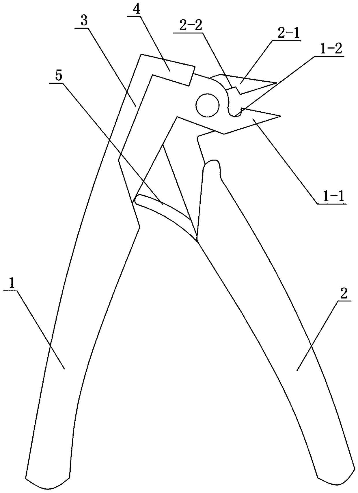
The invention discloses a fiber coating stripping device comprising a first handle and a second handle that are hinged to each other. A first clamping head is arranged at the end portion of the firsthandle; a second clamping head is arranged at the end portion of the second handle; the first clamping head is perpendicular to the first handle; and the second clamping head is perpendicular to the second handle. The first clamping head and the second clamping head have pointed ends and matched cutting edges; a first groove and a second groove are formed at the parts, approaching a hinging point,of the inner sides of the first clamping head and the second clamping head; a pressing part connected with the first handle is arranged at the back of the first clamping head; and a hand protection part extends from the pressing part to the first clamping head. The fiber coating stripping device is based on the jaw design conforming to the human engineering and has advantages of labor saving andvisual peeling process and effect.

Description

technical field [0001] The invention relates to a hand tool, in particular to an optical fiber coating stripping device. Background technique [0002] As a common transmission medium in the field of automation and communication, optical fiber has the advantages of high bandwidth and anti-interference. However, its connection is more difficult than ordinary cables. It is necessary to completely strip off the surface coating of the optical fiber and cut out a flat section for fusion. The optical fiber stripper (Miller pliers) adopts a straight line structure. During the stripping process, the hands are perpendicular to each other, and it is difficult for the operator to visually see the stripping effect and angle, which is easy to cause the angle between the optical fiber and the stripping groove. This leads to uneven peeling of the surrounding wall of the optical fiber, which affects the yield of fusion splicing. Contents of the invention [0003] Purpose of the invention:...

Claims


Application Information

Patent Timeline
Patent Type & Authority Applications(China)
IPC IPC(8): G02B6/245
CPCG02B6/245
Inventor 董豪王艳萍冯瑞万紫吟
Owner NANJING CHINA UNIV INTPROP CO LTD
Learn More