PID controller design method

A design method and controller technology, applied in the field of PID controllers, can solve problems such as massive numerical calculations, unfavorable practical applications, failure to guarantee system stability, gain disturbance robustness, etc., and achieve the effect of reducing degrees of freedom and difficulty

Inactive Publication Date: 2018-11-13
FOSHAN UNIVERSITY
View PDF4 Cites 19 Cited by
  • Summary
  • Abstract
  • Description
  • Claims
  • Application Information

AI Technical Summary

Problems solved by technology

[0010] The frequency-domain design method specifies the gain crossover frequency and phase margin of the system, and solves the parameters of the fractional-order controller according to the robustness criterion. The obtained fractional-order controller can ensure the robustness of the system to the open-loop gain disturbance. Some frequency-domain design methods cannot be directly used in the design of fractional-order PID controllers. Moreover, since there is no clear criterion or method for the selection of gain crossover frequency and phase margin, frequency-domain design methods cannot guarantee that the control system has Optimum Dynamic Response Performance
The time-domain optimization algorithm searches the controller parameters according to the given dynamic performance index, and the obtained controller can make the system achieve good step response following performance, but it cannot guarantee that the system has good stability and robustness to gain disturbance
At the same time, using the time-domain optimization algorithm to search for controller parameters requires a large number of numerical calculations, which is not conducive to practical applications.

Method used


Image

  • PID controller design method
  • PID controller design method
  • PID controller design method

Examples


Embodiment Construction

[0040] The concept, specific structure and technical effects of the present invention will be clearly and completely described below in conjunction with the embodiments and accompanying drawings, so as to fully understand the purpose, features and effects of the present invention. Apparently, the described embodiments are only some of the embodiments of the present invention, rather than all of them. Based on the embodiments of the present invention, other embodiments obtained by those skilled in the art without creative efforts belong to The protection scope of the present invention.

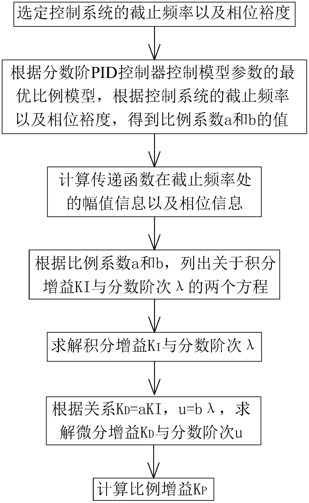
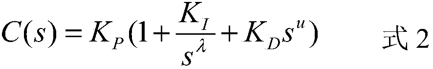
[0041] refer to figure 1 , the present invention discloses a PID controller design method, setting the control model of the PID controller, as shown in formula 2:

[0042]

[0043] where K P is the proportional gain, K I is the integral gain, K D is the differential gain, λ is the integral order, u is the differential order, and s is the Laplace operator;

[0044] K in formula 2 D =aK ...


PUM


Abstract

The invention discloses a PID controller design method. A control model of a PID controller is C(s)=Kp(1+K / S<lambda>+K<D>S) in which K<D>=aK, u=blambda, and a and b represent proportional coefficients respectively, and the control model of the PID controller is reset as C(s)=Kp(1+K / S<lambda>+ aKS<blambda>). A transfer function of a controlled object in the control system is set as G(s)=K / (S<3>+tau1S<2>+tau2S). According to the method, the cutoff frequency omegac and phase margin phim are selected; an optimal proportion model of model parameters is controlled according to the fractional order PID controller, and values of the proportional coefficients a and b are obtained according to the cutoff frequency omegac and phase margin phim; amplitude information and phase information of the transfer function in the cutoff frequency omegac are calculated; two equations related to the integral gain KI and the fractional order lambda are listed; the integral gain KI and the fractional order lambda are solved; a differential gain KD and a fractional order u are solved; and the proportional gain KP is calculated. The proportional relation between the integral gain KI and the differential gain KD of the fractional order PID controller as well as the proportional relation between the integral order lambda and the differential order u are established, the freedom degree of parameters of the fractional order PID controller is reduded, and the difficulty in parameter setting is reduced.

Description

technical field [0001] The invention relates to the technical field of PID controllers. Background technique [0002] At present, the traditional feedback control method based on output error is widely used in the servo system, and this control method is mainly realized by the PID controller. The control model of the traditional PID controller is shown in formula 1: [0003] [0004] where K P is the proportional gain, K I is the integral gain, K D is the differential gain, and s is the Laplacian operator. [0005] The traditional PID controller has the advantages of simple structure and easy implementation. However, the control model of the traditional PID controller is prone to problems such as excessive overshoot and long adjustment time, which cannot meet the performance index requirements of high-performance motion control systems. [0006] Based on the above problems, those skilled in the art improve the control model of the PID controller, and the control mode...

Claims


Application Information

Patent Timeline
Patent Type & Authority Applications(China)
IPC IPC(8): G05B11/42
CPCG05B11/42G05B13/042G05B21/02G06F17/14
Inventor 郑伟佳罗映
Owner FOSHAN UNIVERSITY
Why Eureka
Try Eureka