Battery storage device for new energy automobile with heat radiation function

A storage technology for new energy vehicles and batteries, which is applied in the direction of electric power devices, batteries, electric vehicles, etc. It can solve the problems of inconvenient battery removal, inability to adjust the distance between fan blades and batteries, and inability to effectively adjust the heat dissipation effect of new energy batteries. , to achieve smooth left and right movement, fast fixation, and achieve the effect of fixation

Inactive Publication Date: 2018-11-13
张林
View PDF8 Cites 9 Cited by
  • Summary
  • Abstract
  • Description
  • Claims
  • Application Information

AI Technical Summary

Problems solved by technology

[0005] Aiming at the deficiencies of the prior art, the present invention provides a battery storage device with heat dissipation function for new energy vehicles, which solves the problem that the traditional fan blades are usually fixed and cannot freely adjust the distance between the fan blades and the battery. It is impossible to effectively adjust the heat dissipation effect of the new energy battery, and when the battery needs to be replaced and repaired, the distance between the fan blade and the battery is too close, which brings inconvenience to the process of workers taking out the battery

Method used


Image

  • Battery storage device for new energy automobile with heat radiation function
  • Battery storage device for new energy automobile with heat radiation function
  • Battery storage device for new energy automobile with heat radiation function

Examples


Embodiment Construction

[0032] The following will clearly and completely describe the technical solutions in the embodiments of the present invention with reference to the accompanying drawings in the embodiments of the present invention. Obviously, the described embodiments are only some, not all, embodiments of the present invention. Based on the embodiments of the present invention, all other embodiments obtained by persons of ordinary skill in the art without making creative efforts belong to the protection scope of the present invention.

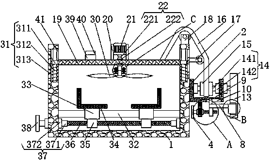
[0033] like Figure 1-5 As shown, the present invention provides a technical solution: a battery storage device with heat dissipation function for new energy vehicles, comprising a first U-shaped plate 1, the left and right sides of the inner wall of the first U-shaped plate 1 are respectively connected with the second slide bar 32 The left and right ends of the second sliding rod 32 are fixedly connected, and the outer wall of the second sliding rod 32 is res...


PUM


Abstract

The invention discloses a battery storage device for a new energy automobile with a heat radiation function. The battery storage device comprises a first U-shaped plate, wherein the right side surfaceof the outer wall of the first U-shaped plate is fixedly connected with the left side surface of the outer wall of a second U-shaped plate; the lower surface of the outer wall of the second U-shapedplate is fixedly connected with the upper surface of a support plate; a first rotating device is clamped with the right side surface of the support plate; the left end of the first rotating device isfixedly connected with the right side surface of a first moveable rod. According to the battery storage device for the new energy automobile with the heat radiation function, due to cooperation of a second moveable rod, a second rotating shaft, a second bearing, a coiling disc, a traction rope, a moveable plate, a motor, a third rotating shaft, a third bearing, the second U-shaped plate and fan blades, the heights of the fan blades can be adjusted, effective heat radiation of a new energy battery can be achieved, the fan blades can be far away from a battery when the battery needs to be repaired and replaced by an operator, and thus convenience can be brought to the operator to replace the battery.

Description

technical field [0001] The invention relates to the technical field of new energy vehicles, in particular to a battery storage device with heat dissipation function for new energy vehicles. Background technique [0002] New energy vehicles refer to the use of unconventional vehicle fuels as power sources (or the use of conventional vehicle fuels and the use of new vehicle power devices), the integration of advanced technologies in vehicle power control and driving, and the formation of advanced technical principles and features Cars with new technologies and structures. [0003] The energy storage of new energy vehicles (oil-electric hybrid vehicles and pure electric vehicles) requires the use of high-performance power batteries. During use, the internal temperature of the battery will rise due to high-current charging and discharging, making the battery temperature exceed its normal temperature. Use temperature, and even cause battery rupture, leakage, fire and explosion, ...

Claims


Application Information

Patent Timeline
Patent Type & Authority Applications(China)
IPC IPC(8): H01M2/10H01M10/613H01M10/6563B60K1/04B60L11/18
CPCB60K1/04B60K2001/0488H01M2220/20H01M10/613H01M10/6563H01M50/20Y02E60/10Y02T10/70
Inventor 崔育宝
Owner 张林
Why Eureka
Try Eureka