
Metasurface-based convex conformal Gregory antenna

A Gregorian and metasurface technology, applied to antennas, electrical components, waveguide horns, etc., can solve problems such as large phase compensation errors, phase error increases, and large phase errors, achieving accurate phase compensation, simple structure, and easy Processing effect

Active Publication Date: 2018-11-13
XIDIAN UNIV
View PDF4 Cites 1 Cited by
  • Summary
  • Abstract
  • Description
  • Claims
  • Application Information

AI Technical Summary

Problems solved by technology

[0004] First of all, the phase compensation method of this antenna is that the electromagnetic wave passes through the metamaterial twice successively, and the wavefront calibration is performed by using the different constitutive parameters of the metamaterial on the propagation path and the different electrical wavelength changes at the same physical distance. The premise of the phase path design of the material layer is to assume that the electromagnetic wave is vertically incident on the reflective surface, and does not consider the change of the incident angle when the electromagnetic wave is obliquely incident, there is a large phase compensation error, and the phase error increases with the increase of the incident angle ;
[0005] Secondly, since the phase compensation of the reflected wavefront of this antenna is based on the fact that the electromagnetic wave passes through the metamaterial layer twice, the degree of matching between the metamaterial and free space is different for different electromagnetic parameters, so the matching between the metamaterial layer and free space The problem will also affect the wavefront calibration results of the antenna, and the resulting phase compensation error will further increase;
[0006] Thirdly, since the required metamaterials of this antenna are realized by loading metal microstructures in the multilayer dielectric plate, not only the structure is more complex, but also the problem of beam alignment of the convex mirror that conforms to the carrier cannot be solved, and the phase error is relatively large

Method used


Image

  • Metasurface-based convex conformal Gregory antenna
  • Metasurface-based convex conformal Gregory antenna
  • Metasurface-based convex conformal Gregory antenna

Examples


Embodiment Construction

[0035] The present invention will be further described below in conjunction with the accompanying drawings and specific embodiments.

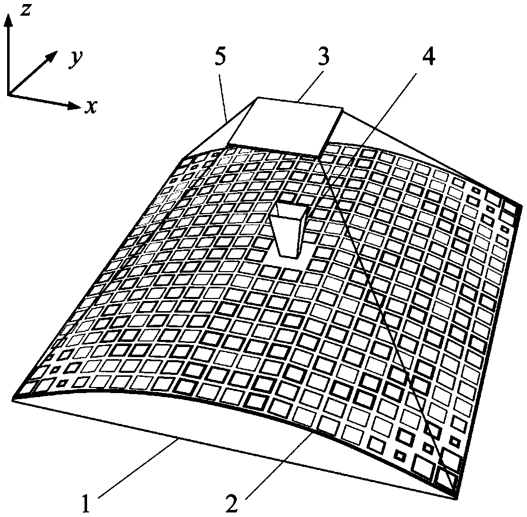
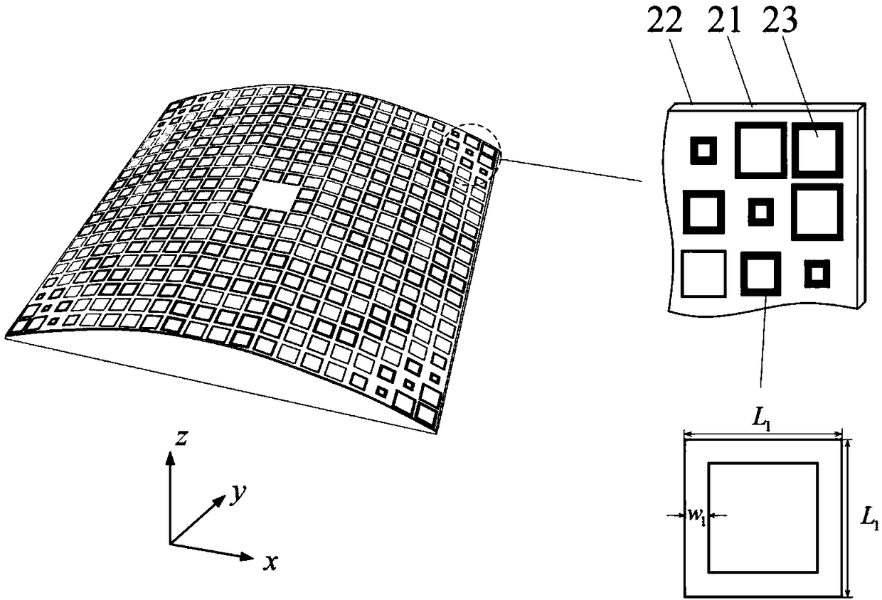
[0036] refer to figure 1 , the present invention includes a carrier 1 , a primary reflector 2 , a secondary reflector 3 , a feed source 4 and a supporting structure 5 . The carrier 1 is located at the bottom of the overall structure of the antenna, the main reflector 2 is conformally inlaid on the upper surface of the carrier 1, the feed source 4 is located in the central hollow position of the carrier 1 and the main reflector 2, and the secondary reflector 3 is located on the front of the feed source 4. Above, it is connected with the main reflector 2 through a supporting structure.

[0037]The carrier 1 adopts a convex structure, and the main reflector 2 is conformal to the carrier 1. The center of the conformal structure is hollowed out, and a feed source 4 is installed in the hollowed out position. The feed source 4 adopts a pyramidal horn...


PUM


Abstract

The invention discloses a metasurface-based convex conformal Gregory antenna, and mainly aims to solve the problems that the existing antenna is high in phase error, complex in structure, and hard torealize convex Gregory wave beam calibration. The metasurface-based convex conformal Gregory antenna comprises a carrier (1), a main reflecting mirror (2), an auxiliary reflecting mirror (3), a feed source (4) and a supporting structure (5); the carrier adopts a convex structure; the main reflecting mirror is conformal with the carrier; each of the main reflecting mirror and the auxiliary reflecting mirror adopts a phase change metasurface structure established based on generalized Snell law, wherein the auxiliary reflecting mirror is located above the focal point of the main reflecting mirrorand has an ellipsoid characteristic phase, and is used for focusing the electromagnetic waves emitted by the feed source to a perifocus of the auxiliary reflecting mirror; the perifocus of the auxiliary reflecting mirror coincides with the focal point of the main reflecting mirror, and the over focus coincides with the phase center of the feed source; and the main reflecting mirror and the auxiliary reflecting mirror are connected through the supporting structure. By virtue of the metasurface-based convex conformal Gregory antenna, wave beam calibration of the convex conformal Gregory antennacan be realized; and meanwhile, the antenna phase compensation error is lowered, the structure is simple, and the antenna can be used for communication and radar.

Description

technical field [0001] The invention belongs to the technical field of antennas, and relates to a Gregorian antenna, which can be used for communication and radar. technical background [0002] Microwave antennas are mainly divided into end-fire, slot, reflector antennas and other types, among which the reflector antenna has the characteristics of high gain performance. The microwave reflector antenna is mainly a parabolic antenna, which uses the collimation effect of the parabolic reflector to convert the spherical wavefront emitted from the feed source at the focal point into an outgoing plane wavefront to form a high-gain pattern. The Gregorian antenna adds an ellipsoidal sub-reflector to the parabolic antenna. Electromagnetic waves are reflected by the sub-reflector and the main reflector to obtain a highly directional radiation pattern. It has been widely used in communications and radar. Compared with the ordinary parabolic antenna, the added sub-reflector is more con...

Claims


Application Information

Patent Timeline
Patent Type & Authority Applications(China)
IPC IPC(8): H01Q13/02H01Q15/00H01Q15/14H01Q15/16H01Q19/19
CPCH01Q13/02H01Q15/0086H01Q15/14H01Q15/16H01Q19/19
Inventor 杨锐高东兴高鸣李冬张澳芳李佳成
Owner XIDIAN UNIV
Learn More