An infrared imaging seeker thermal flow imaging test device
A technology of infrared imaging and testing equipment, applied in the direction of instruments, etc., can solve the problems of high cost, manpower and material resources, long test cycle, etc., and achieve the effect of low cost, simple operation and short test cycle
Active Publication Date: 2016-06-01
AEROSPACE SCI & IND MICROELECTRONICS SYST INST CO LTD
View PDF0 Cites 6 Cited by
- Summary
- Abstract
- Description
- Claims
- Application Information
AI Technical Summary
Problems solved by technology
Although the former is simple, the heating of the hood is uneven and unstable, and the heating temperature is difficult to control
The latter is a large-scale seeker test with a long test period and high cost, requiring a lot of manpower and material resources
At the same time, both methods can only verify the imaging effect of the seeker under hot air conditions, and cannot verify the imaging effects of other heat flows such as carbon dioxide heating the hood
Method used
View moreImage
Smart ImageViewing Examples

Examples
Embodiment Construction
Login to View More PUM
 Abstract
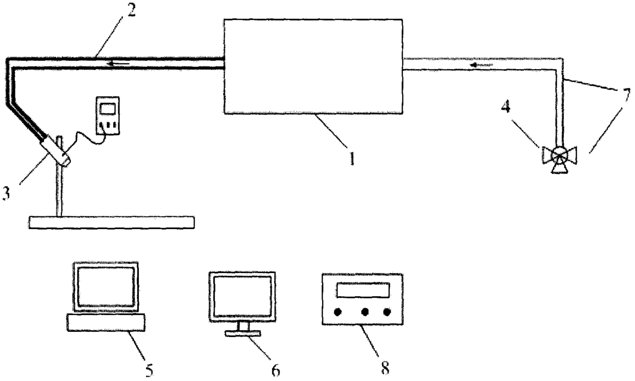
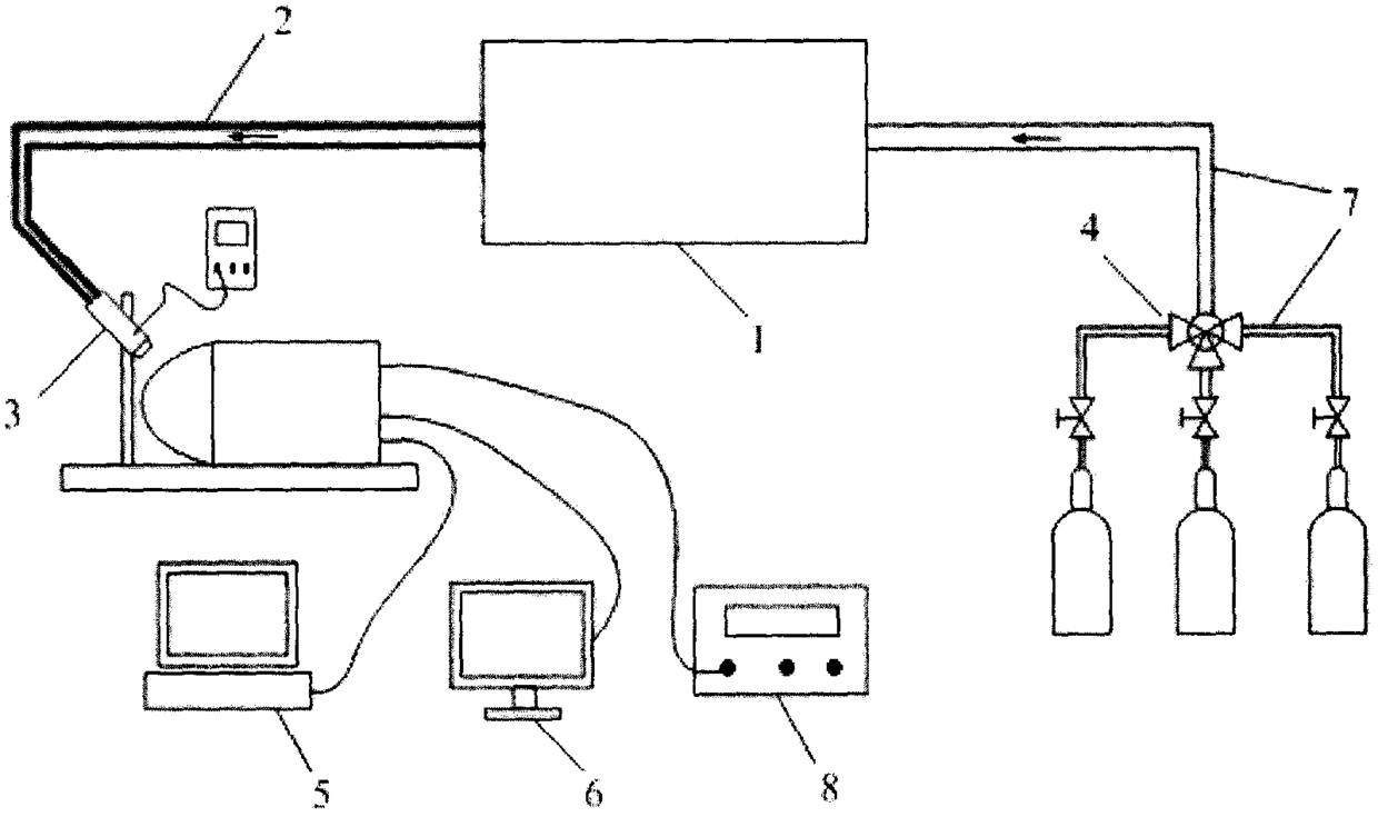
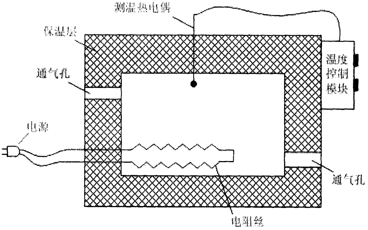
The invention discloses an infrared imaging seeker heat flow imaging test device, which comprises a constant temperature heating chamber, a heat insulation conduit, a nozzle, a multi-channel gas valve, an image acquisition module, and a monitoring module. The multi-channel gas valve is used for mixing different gases. It is output to the constant temperature heating chamber through the conduit; the constant temperature heating chamber is used for constant temperature heating of the gas in the chamber; one end of the heat insulation conduit is connected to the constant temperature heating chamber, and the other end is connected to the nozzle, which is used to insulate and transport the heated gas; the nozzle is used to The gas delivered through the heat-insulated conduit is sprayed to the infrared imaging seeker head cover; the image acquisition module is connected with the infrared imaging seeker to collect and store the image data output by the infrared imaging seeker; the monitoring module is connected to the infrared imaging seeker It is used to observe the infrared image of the infrared imaging seeker in real time. The implementation of the invention can qualitatively simulate the aero-optical effect of the infrared imaging seeker during high-speed flight, and verify the imaging effect of the infrared imaging seeker under the thermal effect condition.
Description
technical field The invention belongs to the technical field of infrared imaging seeker testing, and more particularly relates to an infrared imaging seeker thermal flow imaging testing device. Background technique Infrared optical terminal guidance is the main development direction of the precision guidance technology of today's missile weapon system, and the infrared seeker is the core component. Due to the high-speed flight of the missile (speed greater than Mach 3), the infrared imaging seeker located at the forefront of the missile body is in the process of intense friction with the air flow, the temperature of the seeker head cover rises sharply, and the atmosphere in contact with the head cover is also heated. , both of them produce a large amount of infrared radiation, which brings a lot of stray light interference to the imaging of the infrared imaging seeker. In the ground-to-infrared seeker imaging test process, in order to simulate the aerodynamic heating effect...
Claims
Login to View More Application Information
Patent Timeline
 Patent Type & Authority Patents(China)
IPC IPC(8): G01D18/00
Inventor 史要涛柯才军武春风张燕于翠萍彭小康赵相国李宁
Owner AEROSPACE SCI & IND MICROELECTRONICS SYST INST CO LTD