A gas distribution device and a gas water heater using the device

A gas water heater and distribution device technology, which is applied in the directions of gas fuel burners, gaseous fuel supply/distribution, burners, etc., can solve the difficulty of meeting regional differences, seasonal differences, individual differences among people, and uneven combustion of heat exchangers on one side. , piston or sealing ring is easy to wear, etc., to achieve the effect of convenient, quick and flexible adjustment, uniform and stable combustion flame, and improved work reliability

Active Publication Date: 2021-05-18
NINGBO FOTILE KITCHEN WARE CO LTD
View PDF7 Cites 0 Cited by
  • Summary
  • Abstract
  • Description
  • Claims
  • Application Information

AI Technical Summary

Problems solved by technology

[0004] The defects of the above-mentioned patents are: the number of stages that can be adjusted for combustion firepower is small (that is, the firepower adjustment level is small), and the adjustment gradient is too large, the control of the gas flow is not precise enough, and it is still easy to cause the minimum water temperature to be too high or the maximum water temperature to be too low phenomenon, it is difficult to meet the problems of regional differences, seasonal differences, and individual differences of people, which affects the comfort of users; in addition, the solenoid valve is large in size and high in cost. Considering the internal space and cost of the water heater, the existing gas flow distribution The device also needs to be further improved
[0007] However, this patent opens the nozzles in sequence from right to left through the translation of the piston, that is, the nozzles can only be opened or closed one by one, and cannot be opened or closed multiple times at one time, so the adjustment of the gas flow is not flexible and convenient; in addition, because The number of different nozzles can be opened through the translation of a piston. In order to prevent gas from entering the nozzle on the left side of the piston from the piston or sealing ring, there must be no gap between the outer wall of the piston or the sealing ring and the inner wall of the gas main pipe, and the gas flow rate The adjustment can only be realized by the movement of the one piston, and the piston or sealing ring is easy to wear, resulting in poor sealing; in addition, in order to make the piston or sealing ring move smoothly, lubricating grease is usually applied on the piston and sealing ring, but the grease is easy to Blockage of the nozzle; and, if the piston is worn out and loses its plugging effect, the gas flow regulation of the entire device fails
[0008] In addition, the method of opening the nozzles in sequence makes the fire power concentrated in a certain area, resulting in uneven combustion on one side of the heat exchanger, local high temperature problems, condensed water, and accelerated aging in parts with high frequency of use; in addition , the gas needs to be mixed with air to carry out the combustion reaction, and the air inlets supplying the air are evenly distributed. When burning on one side, the fresh air on the other side does not participate in the combustion, but is directly discharged through the heat exchanger. Outdoor, reducing the thermal efficiency when burning on one side

Method used


Image

  • A gas distribution device and a gas water heater using the device
  • A gas distribution device and a gas water heater using the device
  • A gas distribution device and a gas water heater using the device

Examples


Embodiment 1

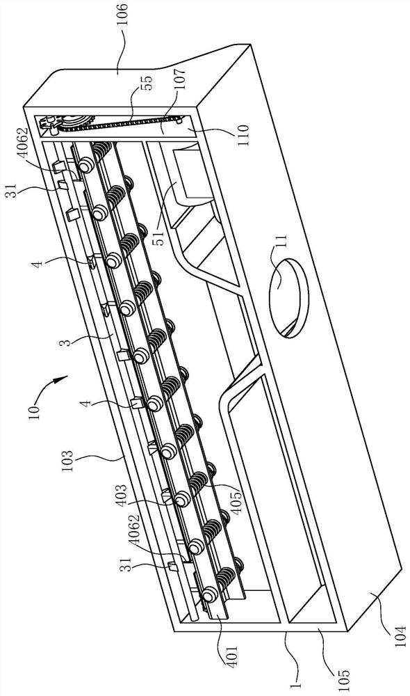
[0092] like Figure 15 As shown, the gas distribution device of this preferred embodiment is used in a gas water heater, and of course it can also be used in a gas wall-hung boiler. The gas water heater includes a burner 101, a gas distribution device 10, and a gas valve group 102 for controlling the gas intake.

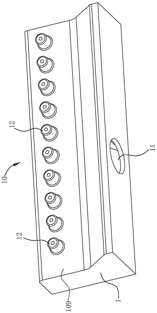
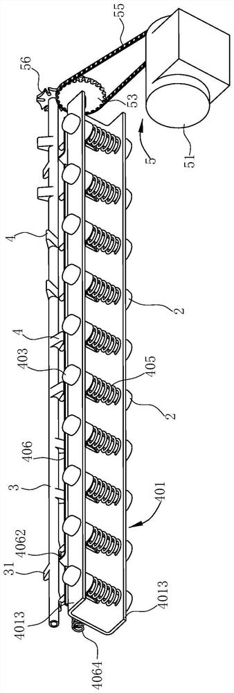
[0093] like Figure 1-14 As shown, the gas distribution device 10 includes a housing 1, a nozzle 12 and a blocking member 2, a rotating shaft 3, a reset member, a driving mechanism, a connecting assembly and a power mechanism 5 arranged in the housing 1, the rotating shaft 3, the blocking member 2 Together with the power mechanism 5, it constitutes a blocking mechanism for blocking the nozzle 12. Housing 1 comprises top plate 103, bottom plate 104, left side plate 105, right side plate 106, connecting plate 107, front side plate 108 and rear side plate 109, top plate 103, bottom plate 104, left side plate 105, right side plate 106 and The rear side plate 109 is int...

Embodiment 2

[0112] like Figures 17-28 As shown, the difference between Embodiment 2 and Embodiment 1 lies in that the power mechanism 5a, reset member, driving mechanism and connecting assembly of this embodiment are different.

[0113] First, the power mechanism 5a of this embodiment includes a motor 51a and a transmission mechanism. The motor 51a is a servo motor. The transmission mechanism includes a primary gear 52a connected to the output end of the motor 51a and a final gear 53a capable of transmitting power to the rotating shaft 3a. , the final gear 53a is arranged on the rotating shaft 3a, and the transmission between the primary gear 52a and the final gear 53a is through a chain 55a.

[0114] The driving structure and connecting components of the present embodiment are as follows: the housing 1a is provided with connecting frames 64 having the same number as the connecting components. 64 is provided with bayonet socket 641.

[0115] like Figures 19-21, 25-28, each of the con...

Embodiment 3

[0124] like Figures 29 to 34 As shown, the difference between Embodiment 3 and Embodiment 1 lies in that the power mechanism 5b, the driving mechanism and the connecting components of this embodiment are different.

[0125] In this embodiment, the power mechanism 5b includes a motor 51b and a transmission mechanism. The motor 51b is arranged on the bottom plate 104 and its power output end passes through the connecting plate 107 to the installation cavity 110. The transmission mechanism is located in the installation cavity 110 and includes a The output end of 51b drives the connected primary gear 52b and the final gear 53b that can transmit power to the rotating shaft 3b. The final gear 53b is arranged on the rotating shaft 3b. The transmission between the primary gear 52b and the final gear 53b is through the intermediate gear 54b.

[0126] In this embodiment, the driving mechanism is a driving block group, and the connecting component is a seesaw 408, specifically as follo...


PUM


Abstract

The invention relates to a gas distribution device and a gas water heater using the device, wherein the gas distribution device includes a casing, a nozzle, a rotating shaft, a power mechanism and a blocking member, and at least one first valve for supplying gas into the casing is provided on the casing. There are at least two air inlets and nozzles arranged at intervals on the side wall of the housing. The rotating shaft extends axially along the direction in which the nozzles are arranged at intervals. The power mechanism is used to drive the rotating shaft to rotate around its own axis, and the blocking member is used to block the nozzles. There are at least two blocking members and each blocking member corresponds to a nozzle, and the blocking members at different positions and in different numbers move toward the nozzle with the rotation of the rotating shaft to block the gas flow entering the corresponding nozzle or move away from the nozzle to Open the corresponding nozzle. There are multiple blocking parts in this way, even if one of the blocking parts is worn out, the other blocking parts can still work normally, and the adjustment of the gas flow can still be carried out, and the fault tolerance rate is high.

Description

technical field [0001] The invention belongs to the technical field of fluid heaters with heat generating devices, and in particular relates to a gas distribution device and a gas water heater using the device. Background technique [0002] There is a defect in the use of gas water heaters or wall-hung boilers, that is, in summer, even if the gas is adjusted to the minimum gas supply, the water temperature is still too hot when showering, and the water temperature is not hot enough in winter. In order to solve the aforementioned problems, many manufacturers have adopted gas distributors (also known as gas sectionalizers or front pipes), that is, control valves are used to control the combustion of different nozzles on the gas distribution pipes, so as to achieve the size of the combustion firepower of water heaters and improve the efficiency of water heaters. range of adaptation. [0003] As shown in "A Gas Water Heater" disclosed by the Chinese Utility Model Patent No. ZL2...

Claims


Application Information

Patent Timeline
Patent Type & Authority Patents(China)
IPC IPC(8): F24H9/20F24H9/18F23N1/00F23K5/00F23D14/48
CPCF23D14/48F23K5/007F23N1/005F24H9/1836F24H9/2035
Inventor 王世平段裘铭金晶徐金金黄启彬
Owner NINGBO FOTILE KITCHEN WARE CO LTD
Why Eureka
Try Eureka