Two-shaft backfill type friction stir spot welding device

A friction stir and spot welding device technology, applied in welding equipment, non-electric welding equipment, metal processing equipment, etc., can solve problems such as short service life, complex power transmission system, and too long lead screw

Active Publication Date: 2018-11-16
HARBIN INST OF TECH AT WEIHAI
View PDF7 Cites 5 Cited by
  • Summary
  • Abstract
  • Description
  • Claims
  • Application Information

AI Technical Summary

Problems solved by technology

The existing backfill friction stir spot welding device has disadvantages such as complex power transmission system, poor stability, easy deformation of the stirring needle and sleeve, poor spot welding effect, short service life, and large overall volume of the device.
[0004] In November 2013, the State Intellectual Property Office published an invention patent application titled: A backfill friction stir welding method and its device, application number: 201310347507.X, although the device realizes backfill friction stir spot welding function, but it still has the following defects: 1. The stirring needle drives the sleeve to rotate through the spline pair, and the inner layer drives the outer layer to rotate. The torque is large, the power requirement is high, and the energy efficiency is low; 2. The transmission mechanism is complex and bulky. It is easy to produce problems such as large moment of inertia, elastic deformation, backlash, movement lag, friction, vibration, noise and wear, and the overall stability is poor; 3. When working, the dynamic force point and resistance force of the stirring needle and the cuff moving up and down The points are not coaxial, there is side load, the stirring needle and the sleeve are deformed, the welding accuracy is low, the effect is poor, the stirring needle, the sleeve and the jacket are easy to wear due to deformation, and the service life is short
4. Double power source and double lead screw respectively drive the stirring needle and the cuff to move up and down. The structure is complex and wastes space. The lead screw is too long to drive and the stability is poor.

Method used


Image

  • Two-shaft backfill type friction stir spot welding device

Examples


Embodiment Construction

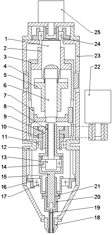
[0016] like figure 1 The shown two-axis backfill friction stir spot welding device includes an outer shell 23 and a stirring head made up of a stirring pin 19, a tubular sleeve 20, and a jacket 18. The jacket 18 is fixed on the lower end of the outer shell 23 for Compress the workpiece to be welded, the sleeve 20 can slide up and down in the sleeve 18, the stirring needle 19 can rotate freely and slide up and down in the sleeve 20, the lower part of the sleeve is a round tube, and the lower part of the stirring needle is inserted The part in the lower part of the sleeve is a cylinder that cooperates with it. The contact surface between the sleeve 20 and the stirring needle 19 and the contact surface between the sleeve 20 and the jacket 18 are all mirror surfaces. A screw pair, the outer side of the nut 2 lower end of the first lead screw pair is provided with a sleeve sleeve 3 that can slide up and down in the outer casing 23, and the upper side wall of the outer casing 23 is ...


PUM


Abstract

The invention relates to a two-shaft backfill type friction stir spot welding device, and relates to a friction stir welding device. The two-shaft backfill type friction stir spot welding device comprises a shell, stirring needles, a sleevelet and a jacket, the shell is internally provided with a first lead screw pair, a nut of the first lead screw pair is provided with a sleevelet sleeve, and thesleevelet sleeve is connected with the sleevelet through a first bearing and a sleevelet rolling spline nut; a second lead screw pair is arranged, the upper end of a screw of the second lead screw pair is arranged in the lower end of a screw of the first lead screw pair in a manner of free sliding in the axial direction, a nut of the second lead screw pair is fixedly connected with the lower endof the screw of the first lead screw pair, the screw of the second lead screw pair is connected with a stirring needle shaft through a second bearing, and the lower end of the stirring needle shaft isconnected with the stirring needle; the rotating directions of the first lead screw pair and the second lead screw pair are opposite, and the ratio of the screw pitches is equal to the inverse ratioof the sleevelet cross sectional area and the stirring needle lower portion cross sectional area; and a first power source for driving a motor rolling spline nut to rotate and a second power source for driving the screw of the first lead screw pair to rotate are arranged. The two-shaft backfill type friction stir spot welding device is light and handy in structure, high in system stability, high in welding accuracy, good in effect and long in service life.

Description

technical field [0001] The invention relates to the technical field of friction stir welding, and specifically relates to a two-axis backfill friction stir spot welding device with light structure, high system stability, high welding precision, good effect and long service life. Background technique [0002] As the society pays more and more attention to energy conservation and environmental protection, lightweight has become the development direction of modern transportation industries such as automobiles and motor vehicles, as well as industrial manufacturing fields such as aerospace. This makes the application of lightweight and high-strength materials such as aluminum alloys and magnesium alloys more and more widely concerned, but at the same time it also puts forward higher requirements for the connection technology of these materials. Due to its light weight and high strength, aluminum alloy is widely used in various industries, especially the automobile and aviation i...

Claims


Application Information

Patent Timeline
Patent Type & Authority Applications(China)
IPC IPC(8): B23K20/12B23K20/26
CPCB23K20/1245B23K20/125
Inventor 周利王瑞张锦标戚家铭黄永宪宋晓国冯吉才
Owner HARBIN INST OF TECH AT WEIHAI
Why Eureka
Try Eureka