A shaft assembly locking and positioning mechanism

A technology of locking and positioning and locking mechanism, which is applied in the directions of internal accessories, assembling machines, containers of machines, etc., can solve the problems of not being able to realize the function of double-axis locking and positioning at the same time, unable to adapt to complex vibration environment, and large stress at the positioning place. , to achieve the effect of simple and compact overall structure design, good environmental adaptability, good axial and radial mechanical properties

Active Publication Date: 2021-04-13
BEIJING AEROSPACE ERA LASER NAVIGATION TECH CO LTD
View PDF6 Cites 0 Cited by
  • Summary
  • Abstract
  • Description
  • Claims
  • Application Information

AI Technical Summary

Problems solved by technology

[0004] The technical problem solved by the invention is: Aiming at the problem that the clamping and positioning method at the positioning point is used in the current prior art, the stress at the positioning point is relatively large and cannot adapt to the complex vibration environment, a locking and positioning mechanism for shafting components is proposed, which overcomes the problem of The positioning accuracy of the traditional rotating mechanism is low, and it is difficult to realize the dual-axis locking and positioning function at the same time

Method used


Image

  • A shaft assembly locking and positioning mechanism
  • A shaft assembly locking and positioning mechanism
  • A shaft assembly locking and positioning mechanism

Examples


Embodiment Construction

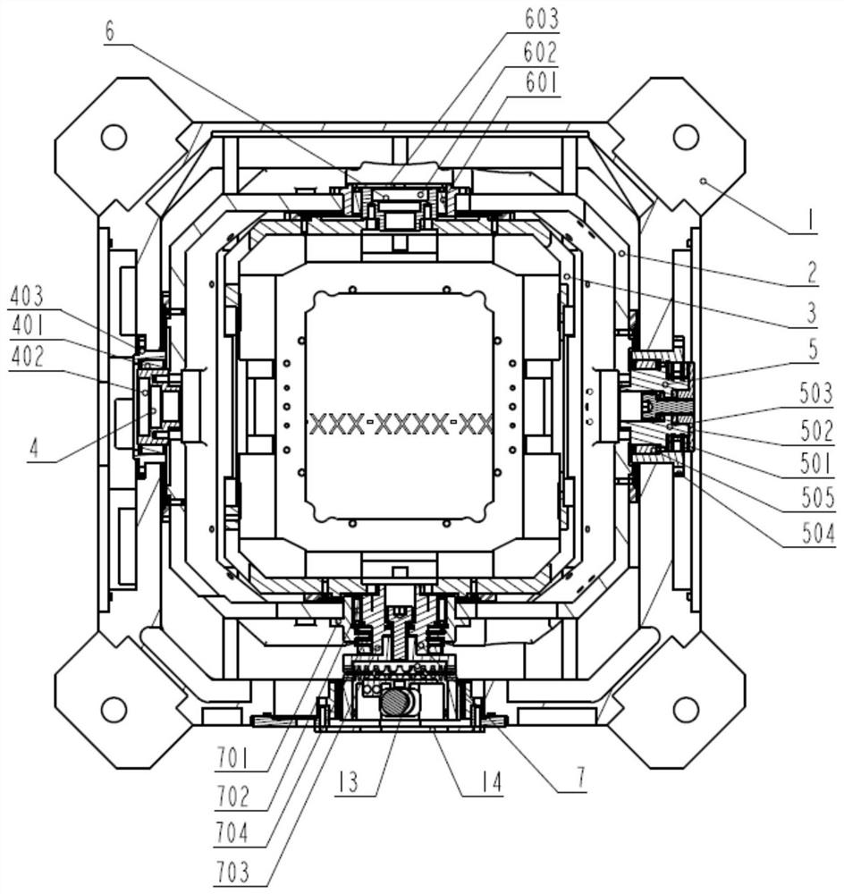
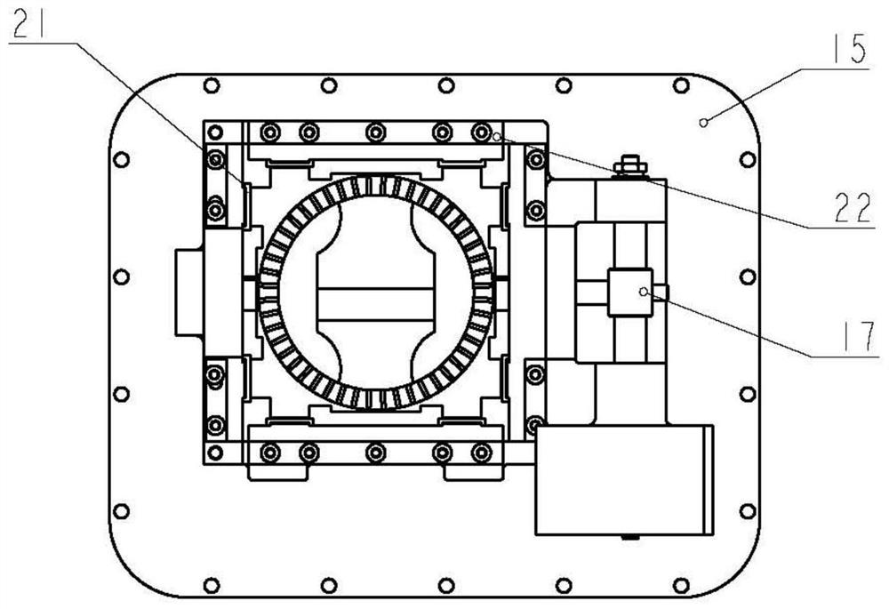
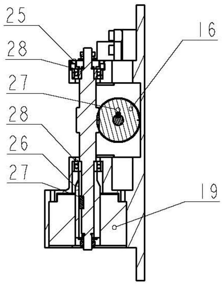
[0025] A shaft assembly locking and positioning mechanism, such as figure 1 As shown, it includes an outer box 1, an outer rotating frame 2, an inner rotating frame 3, a first traveling shaft assembly 4, a restraining shaft assembly 5, a third traveling shaft assembly 6, a locking shaft assembly 7, The fixed-end toothed plate 13 and the locking mechanism 14, the outer rotating frame 2 is connected to the inner side of the outer box body 1 through the first floating shaft assembly 4 and the restraining shaft assembly 5 respectively, and the inner rotating frame 3 is connected through the The third traveling shaft assembly 6 and the locking shaft assembly 7 are connected to the inner side of the outer rotating frame 2, such as figure 2 As shown, the fixed-end sprocket 13 is installed on the outside of the outer rotating frame 2 and locks the outer rotating frame 2 and the inner rotating frame 3 rotated to the designated position by engaging with the locking mechanism 14, wherei...


PUM


Abstract

A shaft assembly locking and positioning mechanism, comprising an outer box body (1), an outer rotating frame (2), an inner rotating frame (3), a first floating shaft assembly (4), and a restraining shaft assembly (5) , the third traveling shaft assembly (7), the locking shaft assembly (6), the fixed-end toothed plate (13), and the locking mechanism (14), through the setting of the fixed-end toothed plate (13), the At the same time, the dual-axis locking and positioning function is completed. This device overcomes the problems of too simple positioning and locking of the traditional mechanism, and the problem of high stress at the positioning position. It can meet the high-precision positioning requirements of the laser pipeline, with tight structure and high stability.

Description

technical field [0001] The invention relates to a locking and positioning mechanism for a shaft assembly, which belongs to the field of high-precision positioning. Background technique [0002] Due to the characteristics of the laser inertial navigation system, the traditional laser strapdown inertial unit requires regular calibration and maintenance, which requires high maintenance and complicated processes. High, put forward the application requirements for the laser strapdown inertial group with the definition of "three self", that is, self-calibration, self-aiming and self-inspection. The "three-self" function means that the laser strapdown inertial group has a dual-axis rotation function, and the self-calibration, self-aiming and self-testing of the laser inertial group can be realized through the rotation modulation of the inner and outer rotating frames. However, the "three-self" laser inertial group requires the inner and outer frames to be absolutely stationary rel...

Claims


Application Information

Patent Timeline
Patent Type & Authority Patents(China)
IPC IPC(8): B65D25/10B65D85/68
CPCB65D25/10B65D85/68B65D2585/6897
Inventor 赵兴法陆煜明雷旭亮严春林陈晓刚刘涛古卫鹏
Owner BEIJING AEROSPACE ERA LASER NAVIGATION TECH CO LTD
Why Eureka
Try Eureka