Biological sample storage system
A biological sample and storage system technology, applied in the field of low-temperature storage of biological samples, can solve the problem of low quality of stored items, achieve the effect of improving storage quality, avoiding direct contact, and ensuring storage quality
- Summary
- Abstract
- Description
- Claims
- Application Information
AI Technical Summary
Problems solved by technology
Method used
Image
Examples
Embodiment 1
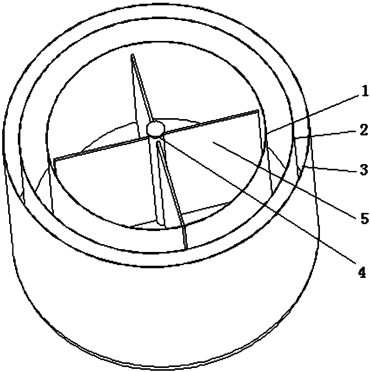
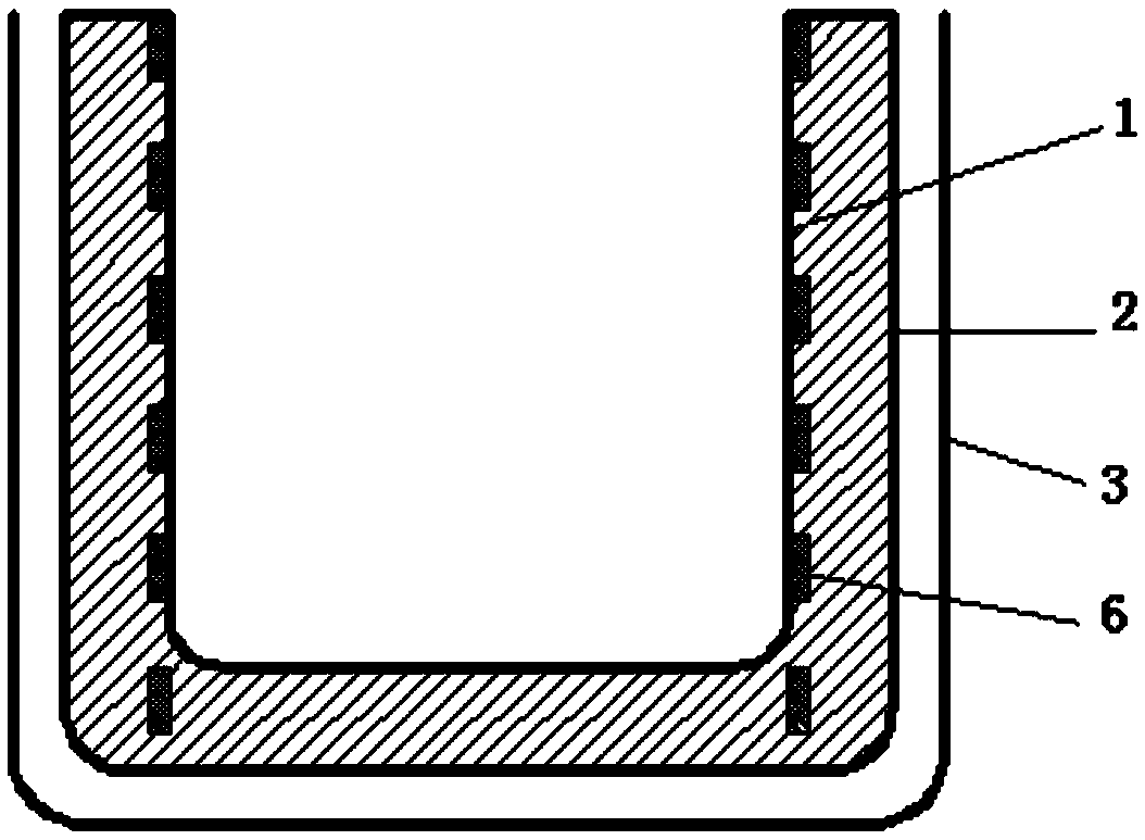
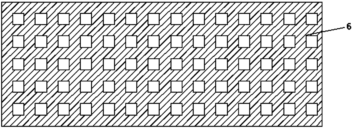
[0069] Such as Figure 1-4 Shown is a specific implementation of a biological sample storage system, including a storage tank, the storage tank includes a tank body with a tank mouth, the tank body includes an inner layer tank body 1, a middle layer tank body 2, an outer layer tank body Tank body 3, the inside of the inner tank body 1 is a biological sample storage area, between the inner layer tank body 1 and the middle layer tank body 2 is a liquid nitrogen storage area, and the outer layer tank body 3 and There is a vacuum area between the intermediate tank bodies 2, and the setting of the vacuum area can isolate the heat transfer between the outside world and the liquid nitrogen storage area. The lid covers the mouth of the tank so that the inside of the inner tank body 1 is a sealed space. The outer wall of the inner tank body 1 is provided with an oxygen-free copper heat conduction grid 6 extending from bottom to top. The inside of the inner tank body 1 is provided wit...
Embodiment 2
[0077] The difference between this embodiment and the above-mentioned embodiment is that, if Figure 5As shown, the liquid nitrogen replenishment system includes a liquid nitrogen replenishment tank 7 and a refrigerator 8, and the refrigerator 8 is sealedly connected to the filling port of the liquid nitrogen replenishment tank 7 and the cold head heat exchanger 81 of the refrigerator 8 goes deep into the In the liquid nitrogen replenishment tank 7, the gas above the liquid nitrogen storage area of the storage tank is connected to the cold head heat exchanger 81 through the first pipeline 9, and the first pipeline 9 is provided with an air inlet Valve 91, the exhaust system includes a second pipeline 10 connecting the liquid nitrogen replenishment tank 7 with the storage tank, and a liquid return valve 101 arranged on the second pipeline 10, the liquid nitrogen An exhaust valve is provided on the pipeline that the nitrogen replenishment tank 7 communicates with the outside w...
Embodiment 3
[0079] The difference between this embodiment and the above-mentioned embodiment is that, if Figure 6 As shown, the liquid nitrogen replenishment system includes a nitrogen production system, and the nitrogen production system includes a liquid nitrogen collection tank 12 and a nitrogen generator 11 arranged at the mouth of the liquid nitrogen collection tank 12, and the liquid nitrogen collection tank 12 is communicated with the liquid nitrogen storage area of the storage tank through the third pipeline 13, the third pipeline 13 is provided with a liquid return valve 131, and the exhaust system includes the liquid nitrogen storage area above the storage tank A fourth pipeline 14 communicating with the outside world, and an exhaust valve 141 arranged on the fourth pipeline 14 . The nitrogen evaporated in the storage tank is discharged through the fourth pipeline 14, and the lost liquid nitrogen is replenished through the nitrogen generator 11, so that the amount of liquid n...
PUM
 Abstract
Description
Claims
Application Information
 - R&D
- Intellectual Property
- Life Sciences
- Materials
- Tech Scout
- Unparalleled Data Quality
- Higher Quality Content
- 60% Fewer Hallucinations
Browse by: Latest US Patents, China's latest patents, Technical Efficacy Thesaurus, Application Domain, Technology Topic, Popular Technical Reports.
© 2025 PatSnap. All rights reserved.Legal|Privacy policy|Modern Slavery Act Transparency Statement|Sitemap|About US| Contact US: help@patsnap.com


