Laser radar

A laser radar and laser technology, applied in the re-radiation of electromagnetic waves, the use of re-radiation, measurement devices, etc., can solve the problems that the laser spacing cannot become very dense, affects the performance of the laser radar, and is difficult to produce and assemble. The effect of minimizing weight, reducing system size and weight, and improving heat dissipation

Active Publication Date: 2018-11-16
HESAI TECH CO LTD
View PDF4 Cites 31 Cited by
  • Summary
  • Abstract
  • Description
  • Claims
  • Application Information

AI Technical Summary

Problems solved by technology

The more columns, the more difficult the production and adjustment, the more complex the process, and the lower the production efficiency; the space utilization rate in the system is low, the focal plane is particularly crowded, the heat is large, and the heat is difficult to be exported, while other parts less fever
The layout of the laser involves the layout of the entire laser emitting device. The size of the light-emitting area of ​​the conventionally used semiconductor laser pulse diode is very small, but in fact, due to the influence of the chip package and the size of the driving circuit, the distance between the lasers cannot become very dense.
In addition, most of the current lidar power transmission methods use wireless power transmission devices, and its specific layout will affect the entire lidar performance

Method used


Image

  • Laser radar
  • Laser radar
  • Laser radar

Examples


Embodiment 1

[0056] A laser radar, comprising a rotor 1, a laser emitting system and a receiving system, the rotor 1 has a mutually isolated launching cabin 13 and a receiving cabin 14, the laser emitting system is arranged in the launching cabin 13, and the receiving system set in the receiving cabin 14,

[0057] The laser emitting system includes a laser emitting device 201, the laser emitting device 201 includes a laser 2015 support 2011, a transmitting circuit group 2012, a transmitting circuit support 2013 and at least one laser emitting board 2014, the laser 2015 support 2011 and the emitting The circuit support 2013 is arranged at intervals, the laser emitting board 2014 is installed on the support 2011 of the laser device 2015, and at least one laser device 2015 is arranged on the laser emitting board 2014; the transmitting circuit group 2012 is installed on the transmitting circuit support 2013 Above, the emitting circuit group 2012 is electrically connected to the laser emitting ...

Embodiment 2

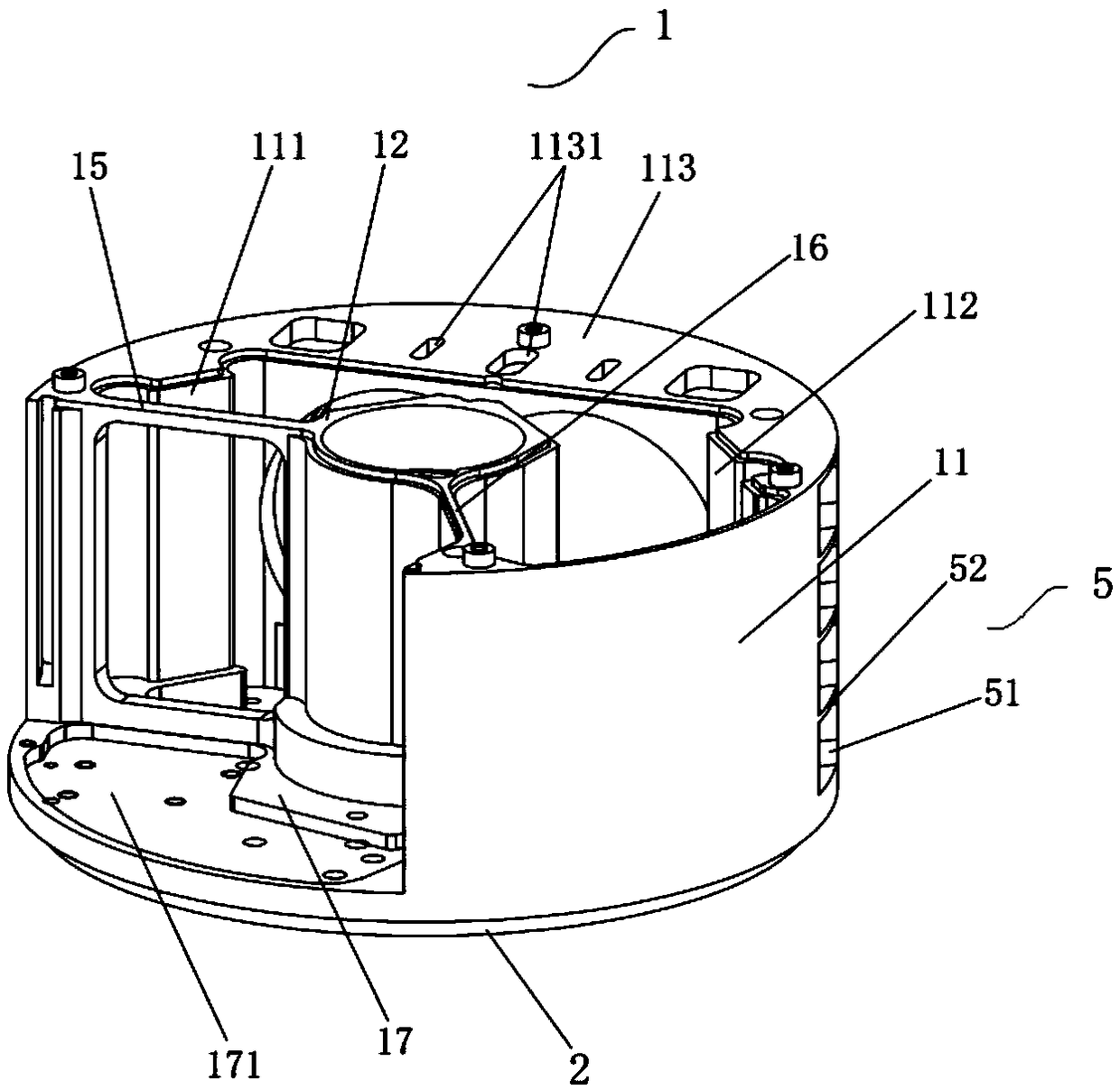
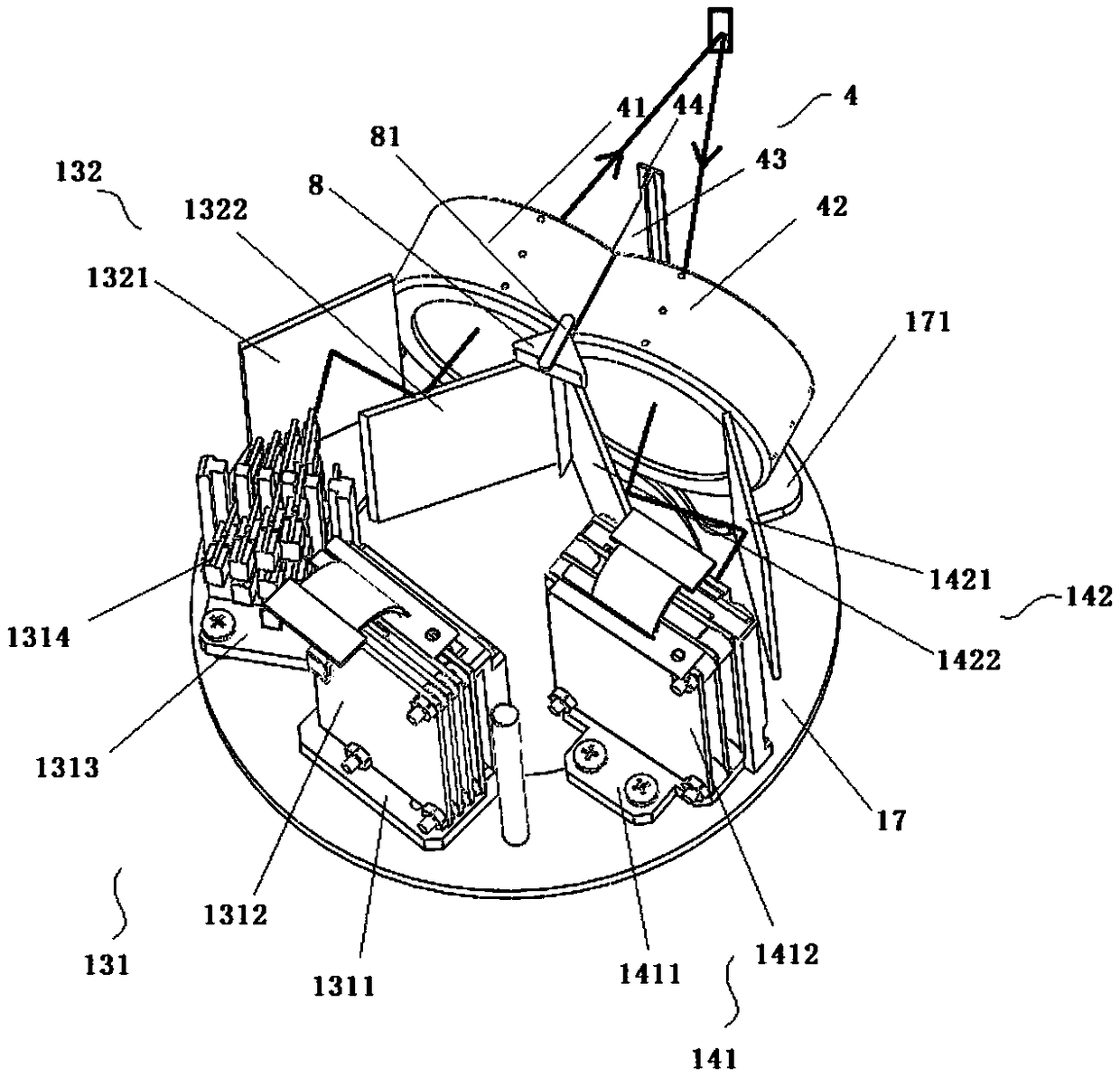
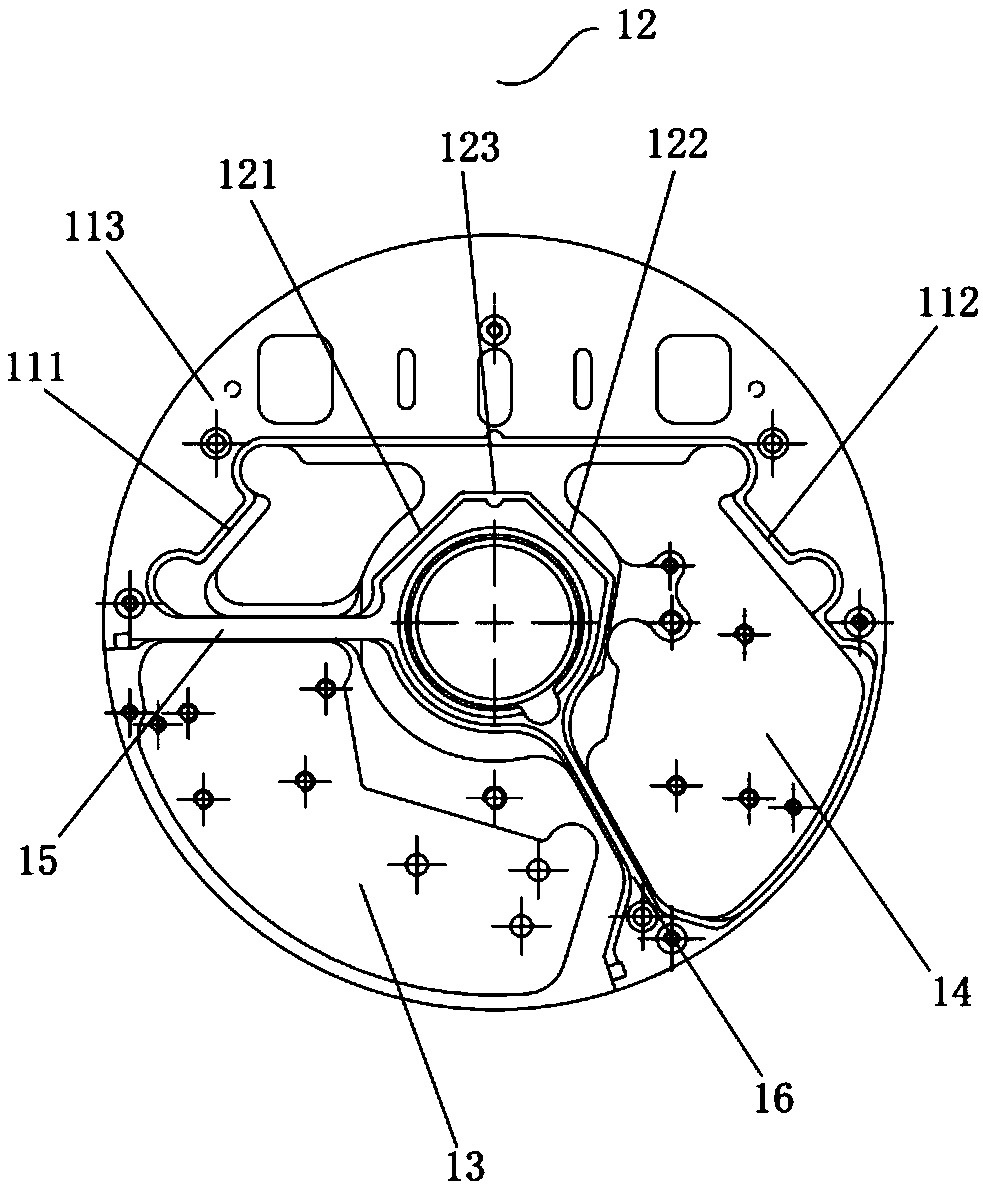
[0065] A lidar device, see Figure 1 to Figure 12 , the lidar device includes a rotor 1, the rotor 1 includes an outer cylinder 11 and an inner cylinder 12, the wall of the outer cylinder 11 is provided with a mounting structure for installing the receiving lens group 301 and the emitting lens group 203, so A third counterweight structure 5 is distributed on both sides of the safety structure, and the third counterweight structure 5 includes a counterweight structure I and a counterweight structure II, and the counterweight structure I and the counterweight structure II include a plurality of first A groove 51. Preferably, the structures of the plurality of first grooves 51 may be the same or different. As a preferred embodiment, in this embodiment, take the plurality of first grooves 51 forming the third counterweight structure 5 as an example: the third counterweight structure includes 12 first grooves 51, specifically included in the 4 rectangular grooves arranged in a str...

Embodiment 3

[0107] to combine Figure 13 to Figure 17 As shown, a laser emitting device includes a laser bracket 2011, a transmitting circuit group 2012, a transmitting circuit bracket 2013, at least one laser emitting board 2014 and a plurality of flexible electrical connectors,

[0108] The laser bracket 2011 and the transmitting circuit bracket 2013 are arranged at intervals, the laser emitting board 2014 is mounted on the laser bracket 2011, and at least one laser 2015 is arranged on the laser emitting board 2014;

[0109] The transmitting circuit group 2012 is installed on the transmitting circuit bracket 2013, and the transmitting circuit group 2012 is connected to the laser emitting board 2014 through the flexible electrical connector.

[0110] like Figure 14 and Figure 15 As shown, the laser bracket 2011 includes a second bottom plate 20111 and a first side plate 20112, the second bottom plate 20111 is connected to the first side plate 20112, and the first side plate 20112 has...


PUM


Abstract

The invention provides a laser radar which comprises a rotor, a laser emission system and a reception system. The rotor comprises an emission chamber and a reception chamber isolated from the emissionchamber, the laser emission system is arranged in the emission chamber, and the reception system is arranged in the reception chamber. The laser emission system comprises a laser support which is used to fix at least one laser emission plate. A laser radar of higher wire harness can be realized via the arrangement manner of the laser emission plate on the laser support and the arrangement mannerof the laser emitters, a laser array is distributed in a non-uniform way so that low wire harness can realize high vertical angle resolution; and the rotor is provided with a third counterweight structure, so that counterweight is adjusted, heat radiation is more effective, and the laser radar can be light.

Description

technical field [0001] The invention relates to the technical field of laser radar, in particular to a laser radar. Background technique [0002] As an important part of the environment perception hardware system of smart cars, Lidar (LI DAR) undertakes important tasks such as roadside detection, obstacle recognition, and real-time localization and mapping (SLAM) in automatic driving. The LI DAR system consists of a laser emitting system and a receiving system. The laser transmitter system generates and emits light pulses, hits the object and reflects back, and is finally received by the receiver. The receiver accurately measures the travel time of the light pulse from when it is emitted to when it is reflected back. Because light pulses travel at the speed of light, the receiver will always receive the previous reflected pulse before the next one is sent. Given that the speed of light is known, travel time can be converted into a measure of distance. LiDAR can accuratel...

Claims


Application Information

Patent Timeline
Patent Type & Authority Applications(China)
IPC IPC(8): G01S7/481
CPCG01S7/484G01S7/486G01S17/931G01S7/481G01S7/4815G01S7/4813G01S7/4817G01S17/08
Inventor 李家盛向少卿
Owner HESAI TECH CO LTD
Why Eureka
Try Eureka