Li-Fi communication protocol based communication control system

A communication protocol and control system technology, applied in the field of optical communication, can solve the problems of lack of effective Li-Fi receiving modules, no power matching characteristics, high clock signal delay, etc., to achieve improved energy utilization, high power adaptation characteristics and Versatility, low power consumption effect

Inactive Publication Date: 2018-11-16
苏州大贝岩电子科技有限公司
View PDF4 Cites 2 Cited by
  • Summary
  • Abstract
  • Description
  • Claims
  • Application Information

AI Technical Summary

Problems solved by technology

[0003] In view of the above-mentioned prior art, the purpose of the present invention is to provide a communication control system based on the LI-Fi communication protocol, which aims to solve the problem of clock signal implementation for Li-Fi encoding due to the existence of parasitic charges and residual charges in the prior art. Technical problems of high time delay, low precision, lack of effective Li-Fi receiving module and no power matching characteristics

Method used


Image

  • Li-Fi communication protocol based communication control system
  • Li-Fi communication protocol based communication control system

Examples


Embodiment 1

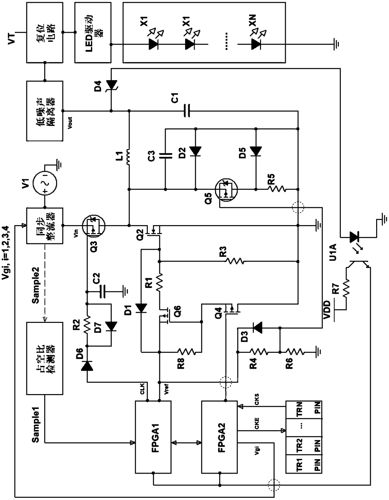
[0044]The first programming logic gate array FPGA1 is used to control the duty ratio of the power supply; the second programming logic gate array FPGA2 is used to control the residual charge discharge and cut off the no-load power supply; the first field effect transistor Q3 receives the first programming logic The duty cycle modulation clock CLK output by the gate array FPGA1 is turned on or off; the oscillation circuit has a discharge circuit structure, receives the first modulated power output by the first field effect transistor, and receives the output by the second programming logic gate array FPGA2 Control the clock and compensate or discharge the first modulation power output by the first field effect transistor Q3; the second field effect transistor Q2 is controlled by the oscillation circuit and forms a step-down switch circuit structure with the first field effect transistor Q3; low noise isolation device, isolated oscillating circuit and communication load circuit. ...


PUM


Abstract

The invention provides an Li-Fi communication protocol based communication control system. The invention relates to the technical field of optical communication and solves technical problems of high implementation time delay and low precision of clock signals used for Li-Fi coding due to existence of parasite charges and residual charges, deficiency of an effective Li-Fi receiving module and deficiency of a power source matching property in the prior art. The system mainly includes a power source and a communication load circuit; a first FPGA; a second FPGA connected with a photosensitive amplification circuit; a first field effect tube receiving a duty ratio modulation clock output by the first FPGA and turning on or turning off the power source; a vibration circuit receiving first modulation power source output by the first field effect tube, receiving a control clock output by the second FPGA and compensating or releasing the first modulation power source output by the first field effect tube; a second field effect tube controlled by an oscillation circuit and form a voltage drop switch circuit structure together with the first field effect tube; a duty ratio detector. The invention is used for Li-Fi communication system design.

Description

technical field [0001] The invention relates to the technical field of optical communication, in particular to a communication control system based on the LI-Fi communication protocol. Background technique [0002] With the development of intelligent communication technology, power line carrier and wired interconnection have gradually evolved into radio interconnection. Nowadays, radio interconnection has also taken an important step towards the future, and Li-Fi optoelectronic interconnection has appeared. Li-Fi photoelectric interconnection currently mainly has difficulties in realizing the lossless transmission of signal clocks. Due to the parasitic charge of the switch and the accumulation of the residual charge of the capacitive and inductive devices in the power supply circuit and the drive circuit, when the power is turned on next time, the amplitude of the impact charge at the moment of turning on is very high, and it is easy to be damaged after being superimposed w...

Claims


Application Information

Patent Timeline
Patent Type & Authority Applications(China)
IPC IPC(8): H04B10/116H02M1/32H02M3/158
CPCH02M1/32H02M3/158H04B10/116
Inventor 黄建中
Owner 苏州大贝岩电子科技有限公司
Why Eureka
Try Eureka