Transmission line remote monitoring system based on internet of things

A remote monitoring system and transmission line technology, applied in transmission systems, electrical components, measuring devices, etc., can solve the problem of data monitoring of the running state of equipment that cannot be operated, cannot be adjusted by the system, and cannot reflect the current, voltage and equipment variation of equipment operation. Bit signal and other problems, to facilitate inspection, ensure system performance, and control costs

Inactive Publication Date: 2018-11-16
HEFEI LANGJIN ANTI COUNTERFEITING TECH CO LTD
View PDF0 Cites 5 Cited by
  • Summary
  • Abstract
  • Description
  • Claims
  • Application Information

AI Technical Summary

Problems solved by technology

The existing transmission line monitoring system transmits the captured video signal to the monitoring terminal, which can only monitor the appearance and operation status of important equipment in the power system, but cannot reflect the current, voltage and equipment displacement signals of the equipment, and cannot monitor the operating equipment. monitoring of the operating status data, let alone timely adjustments to the system

Method used


Image

  • Transmission line remote monitoring system based on internet of things

Examples


Embodiment 1

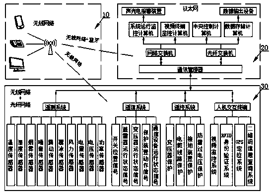
[0033] A transmission line remote monitoring system suitable for the Internet of Things, such as figure 1 As shown, it includes a general control system and a station control system; the general control system includes a human-computer interaction application terminal 1, a central controller 2 and a data processor 3; the station control system includes a human-computer interaction scheduling terminal 10, a monitoring center 20 and a remote control system terminal (RTU) 30; the remote control system terminal (RTU) 30 includes a telemetry system 301, a remote signaling system 302, a remote control system 303 and a human-computer interaction auxiliary system 304; inside the general control system, the station The internal control system and between the master control system and the station control system all use the comprehensive communication method and communication technology of the Internet of Things to realize data transmission.

[0034] Its working principle and function: t...

Embodiment 2

[0036] This embodiment is further optimized on the basis of the above embodiments. Further, the telemetry system 301 includes a temperature sensor, a humidity sensor, a smoke sensor, a noise sensor, a vibration sensor, an ice sensor, a wind sensor, a power sensor, a voltage sensor, power sensor. Each sensor of the telemetry system 301 is used to monitor the temperature, humidity, smog, noise, vibration, icing, wind and other equipment operation status signals of the monitoring points of the transmission line at regular intervals, as well as the electric quantity, voltage, power factor of the electrical equipment in each circuit, etc. The electrical quantity is measured and sent to the monitoring center 20 for analysis, recording and storage.

Embodiment 3

[0038] This embodiment is further optimized on the basis of the above embodiments. Further, the remote signaling system 302 includes switch position signals, lightning arrester operating status signals, transformer operating status signals, protection device action signals, and communication equipment operating status signals. The remote signaling system 302 transmits protection signals such as switch position signals, arrester operating status signals, transformer operating status signals, protection device action signals, and communication equipment operating status signals to the monitoring center 20 for analysis, recording, and storage.


PUM


Abstract

The present invention discloses a transmission line remote monitoring system based on the internet of things. The system comprises a main control system and a station control system; the main controlsystem comprises a man-machine interaction application terminal, a central control unit and a data processor; the station control system comprises a central control unit dispatching terminal, a monitoring center and a remote terminal unit (RTU); and the RTU comprises a remote metering system, a telecommand system, a remote control system and a man-machine interaction auxiliary system. The transmission line remote monitoring system is based on the various sensing technologies and communication means of the internet of things to permeate the man-machine interaction to the terminal, the dispatching terminal and the application terminal of the system to perform remote monitoring and management of the transmission line system, is accurate in location and rapid in reaction, reduces the expenditure of manpower and material resources and achieves automation and intelligence of the transmission line system.

Description

technical field [0001] The invention relates to the field of transmission line detection and management, in particular to a transmission line remote monitoring system suitable for the Internet of Things. Background technique [0002] In recent years, with the deepening reform of the power system management system, the power grid system has developed rapidly towards automation and intelligence. In the field of transmission line inspection and management, limited by the wide distribution of transmission lines and complex distribution environments, especially the harsh environment of transmission lines in marginal areas, manual inspections not only cost a lot of manpower and material resources, but also need to bear great risks. Automatic remote monitoring of manual inspections came into being. The existing transmission line monitoring system transmits the captured video signal to the monitoring terminal, which can only monitor the appearance and operation status of important ...

Claims


Application Information

Patent Timeline
Patent Type & Authority Applications(China)
IPC IPC(8): H04L29/08G01D21/02
CPCH04L67/12G01D21/02
Inventor 邵洪贵
Owner HEFEI LANGJIN ANTI COUNTERFEITING TECH CO LTD
Why Eureka
Try Eureka