Water collection pit anti-floating integral formwork system and installing method for formwork system

A technology of formwork system and installation method, which is applied in the direction of construction and infrastructure engineering, can solve the problems of large quantity and density requirements, affecting the quality of concrete molding, and the inability to vibrate concrete, so as to reduce the installation strength and make the quality easier to control. The effect of reducing workload

Inactive Publication Date: 2018-11-20
CHINA METALLURGICAL CONSTR ENG GRP
View PDF3 Cites 5 Cited by
  • Summary
  • Abstract
  • Description
  • Claims
  • Application Information

AI Technical Summary

Problems solved by technology

[0003] Due to the light weight and insufficient strength of the formwork in the above two methods, it is necessary to use anti-floating steel pipes or tie rods for anti-floating and side formwork support, and the number and density of settings are relatively large. In addition, the formwork needs to be concreted after use. Demolition after final setting and maintenance is time-consuming and labor-intensive, affecting the construction period
In addition, when pouring concrete, the concrete under the bottom form cannot be vibrated, which will affect the molding quality of the concrete

Method used


Image

  • Water collection pit anti-floating integral formwork system and installing method for formwork system
  • Water collection pit anti-floating integral formwork system and installing method for formwork system
  • Water collection pit anti-floating integral formwork system and installing method for formwork system

Examples


Embodiment

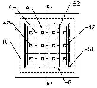
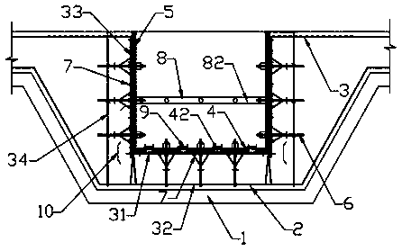
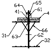
[0026]As shown in the figure, this embodiment provides a sump anti-floating integrated formwork system, which includes a coverless box-shaped formwork assembled from a plurality of side forms 5 and bottom forms 4 and placed in the box-shaped formwork. The support system 8, the bottom form 4 and the side form 5 are respectively fixedly installed on the bottom reinforcement and the side reinforcement of the reinforcement support 3, and the bottom form 4 and the side form 5 are concrete prefabricated slabs with reinforcement mesh inside, and Between the bottom form 4 and the bottom steel bar, between the side form 5 and the side steel bars, a plurality of segmented water stop screws 6 distributed in a lattice shape are installed; A plurality of vibrating holes 42 are evenly distributed among them, and the vibrating holes 42 are rectangular, and the distance between adjacent vibrating holes 42 is 500-800mm, and the specific distance needs to be set according to the effective vibrat...


PUM


Abstract

The invention discloses a water collection pit anti-floating integral formwork system and an installing method for the formwork system. The formwork system comprises a coverless box type formwork anda supporting system arranged in the box type formwork, wherein the box type formwork is formed by assembling a plurality of side dies and a bottom die. The bottom die and the side dies are fixedly arranged on bottom steel bars and side face steel bars of a steel bar support correspondingly. The bottom die and the side dies are concrete prefabricated plates internally provided with steel bar nets,and a plurality of segmented water stop screws are arranged between the bottom die and the bottom steel bars and between the side dies and the side face steel bars, wherein the segmented water stop screws are distributed in a grid-like manner. A plurality of vibration holes are evenly distributed in the bottom die and between the water stop screws. During installation, the segmented water stop screws, the bottom die and the side dies are installed, and then the supporting system is arranged in the box type formwork formed by assembling the side dies and the bottom die. According to the obtained water collection pit anti-floating integral formwork system and the installing method for the formwork system, formwork removal is not needed, time and labor are saved for formwork installation, andthe construction period is short.

Description

technical field [0001] The invention relates to the anti-leakage technology of sump pits in building construction, in particular to an anti-floating integrated formwork system for sump pits and an installation method for the formwork system. Background technique [0002] When the foundation pit is excavated in construction engineering, if the groundwater level is relatively high and the base level is below the groundwater level, it is necessary to set up a sump pit, and excavate drainage ditches along the bottom of the pit or in the center to allow water to flow into the sump pit, and then Take it away with a sewage pump (submersible sewage pump). The cross section of the sump is U-shaped and consists of a bottom plate and a side wall. The sump is generally composed of a base layer, a concrete cushion, a waterproof layer and a reinforced concrete layer from the inside to the outside. When pouring the outermost reinforced concrete layer, according to the design elevation and...

Claims


Application Information

Patent Timeline
Patent Type & Authority Applications(China)
IPC IPC(8): E02D19/22
CPCE02D19/22E02D2250/0007
Inventor 鄢光军
Owner CHINA METALLURGICAL CONSTR ENG GRP
Why Eureka
Try Eureka