Electric steering device transmission for rear-view mirror of car

A technology of electric steering gear and car rearview mirror, applied in the directions of instruments, vehicle parts, installation, etc., can solve the problems of over-the-top, different friction, and the slippage mechanism cannot work.

Inactive Publication Date: 2002-07-31
王振惠
View PDF5 Cites 4 Cited by
  • Summary
  • Abstract
  • Description
  • Claims
  • Application Information

AI Technical Summary

Problems solved by technology

[0002] The electric steering gear of the automobile rearview mirror is installed and fixed in the rearview mirror housing to adjust the angle of the mirror. The driver can easily adjust the field of view according to his own driving habits while sitting in the cab. The electric steering used in domestic automobiles The gears are all imported from abroad. Imported products generally adopt two kinds of worm gear transmission or planetary gear transmission. The disadvantage of the worm gear transmission method is that it will make a lot of noise when it is at the extreme position such as the end or top, and it is difficult to manually adjust. The planetary gear transmission The disadvantage of the method is that the air travel is large and the noise is large
Some foreign advanced developed countries also have certain reports on the transmission mechanism technology of the electric steering gear of the automobile rearview mirror. For example, the U.S. patent "automotive mirror adjustment gear device" with the patent No. Mechanism, in order to avoid the jamming phenomenon at the limit position, its structure is such that the output shaft of the motor adopts a worm, which meshes with the worm wheel, and the worm wheel is integrated with another worm, and the worm is meshed with another worm wheel, and at the same time The worm wheel becomes the friction driving wheel again, and is connected to the friction driven wheel sleeved on the shaft through the end face bonding. The friction driven wheel and the gear are connecte...

Method used


Image

  • Electric steering device transmission for rear-view mirror of car
  • Electric steering device transmission for rear-view mirror of car
  • Electric steering device transmission for rear-view mirror of car

Examples


Embodiment 1

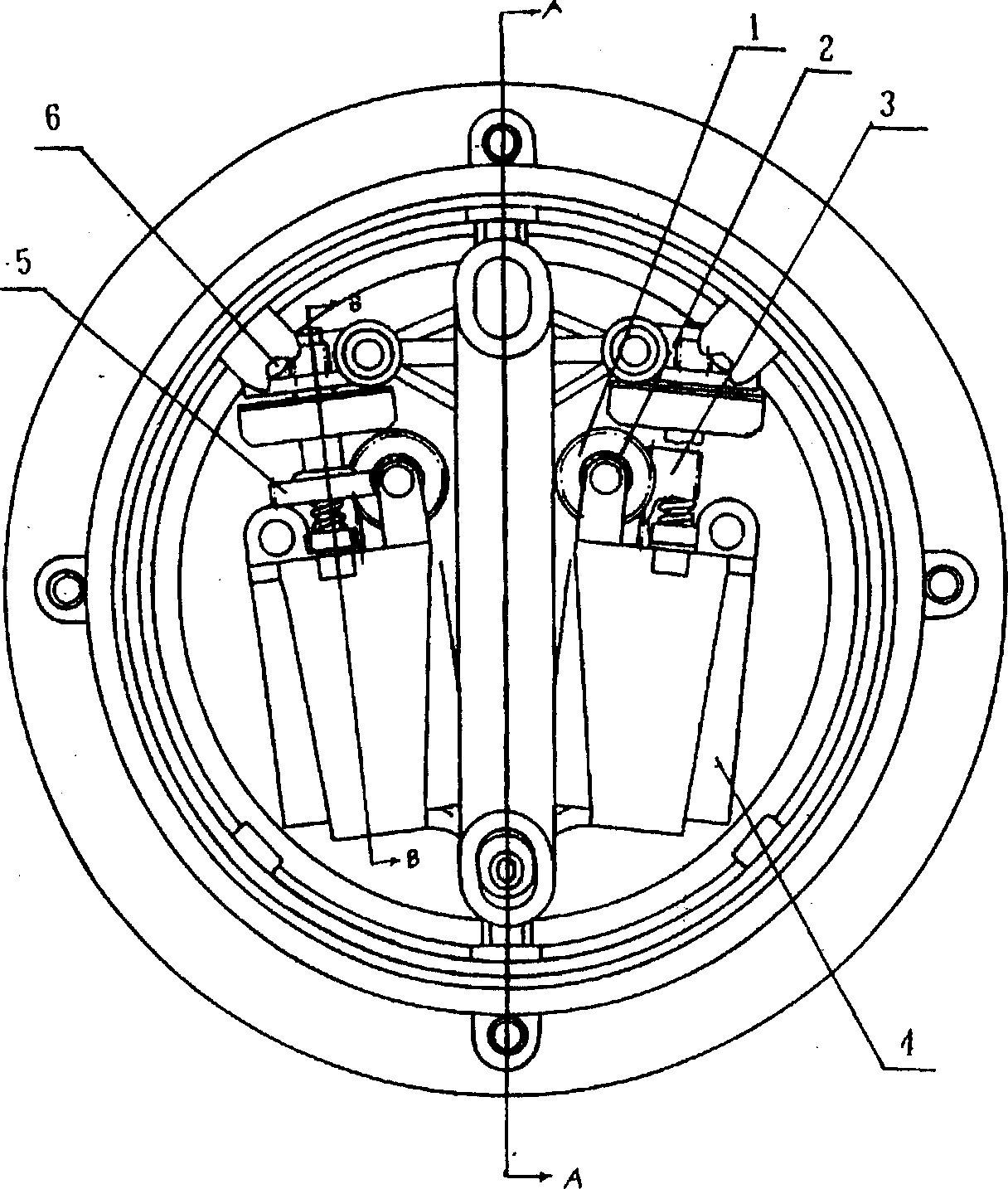
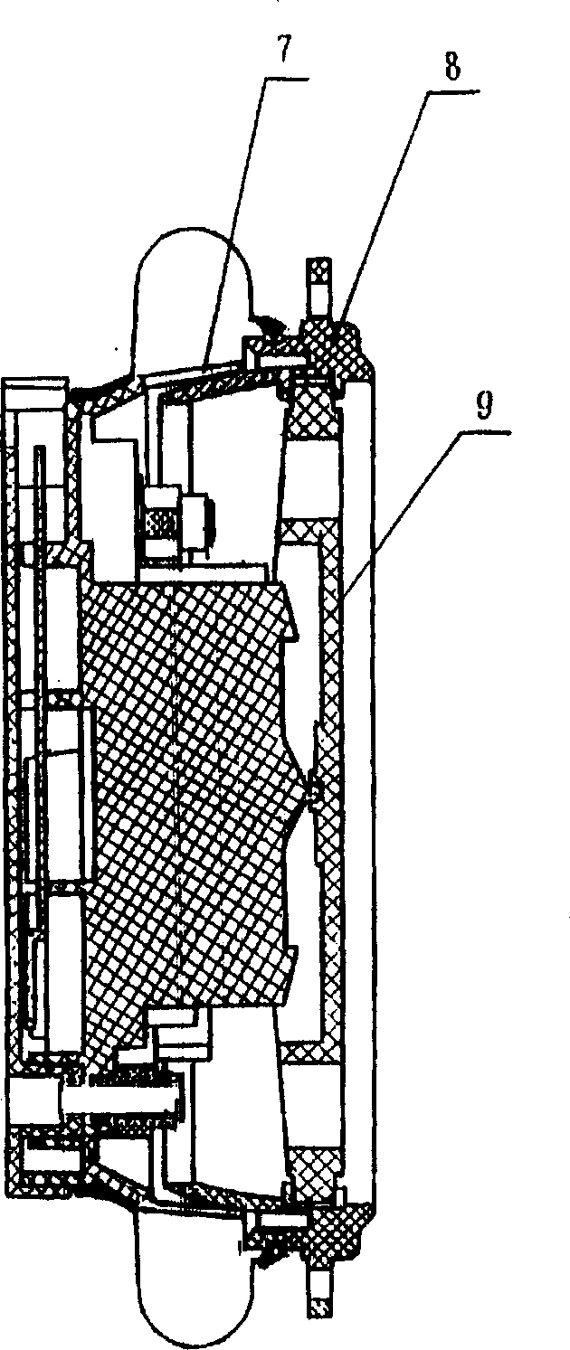
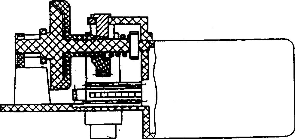
[0017] Embodiment 1. This automobile rearview mirror electric steering gear comprises motor 4, sphere cover 8, rotating sphere 7, is fixed with motor with motor pressure plate on the rotating sphere, and motor output shaft is connected with a first-level worm screw 3, a first-level The worm meshes with a first-stage worm gear 1, and the shaft center of the first-stage worm wheel is connected with a second-stage worm 2 through a semicircular shaft. The secondary worm gear 5 on the output shaft assembly, the secondary worm gear is positioned with the semi-circular shaft of the driving wheel, and is vacantly sleeved on the transmission shaft of the driven wheel assembly, and the end surface of the driving wheel is covered with a spring seat 12, which is connected with the nut 14 on the transmission shaft Between support has spring 13. The friction end surface of the driving wheel 11 has a concave cross-section with an inclined edge, which fits the friction end surface of the driv...

Embodiment 2

[0019] Embodiment 2. The friction slipping mechanism is on the driving wheel transmission shaft 15 of the fixed driving wheel, and is also connected with the worm wheel 5 in the fixed secondary worm gear reduction mechanism, and the axle sleeve is provided with a nut 14, between the nut and the sleeve frame 17 fixing the axle. A spring 13 is supported between them, and the driving wheel fits a driven wheel 10 friction end surface fixed on the driven wheel transmission shaft 16 through the friction end surface, and the shaft is also connected to the pinion of the fixed meshing rack, and others are as in embodiment 1.


PUM


Abstract

An electric driver for controlling the back-view mirror is aimed at reducing idle running and noise and benefiting manual regulation, and has a rack bar which is fixed to spherical sleeve and engaged with the top gear of output axle assemblage. It features that the output axle assemblage behind the speed variator of electric motor has a friction sliding mechanism. Its advantages are short idle running, low noise, smooth rotation and not jamming easily.

Description

technical field [0001] The invention relates to the technical field of an electric steering gear transmission device for an automobile rearview mirror. Background technique [0002] The electric steering gear of the automobile rearview mirror is installed and fixed in the rearview mirror housing to adjust the angle of the mirror. The driver can easily adjust the field of view according to his own driving habits while sitting in the cab. The electric steering used in domestic automobiles The gears are all imported from abroad. Imported products generally adopt two kinds of worm gear transmission or planetary gear transmission. The disadvantage of the worm gear transmission method is that it will make a lot of noise when it is at the extreme position such as the end or top, and it is difficult to manually adjust. The planetary gear transmission The disadvantage of the method is that the air travel is large and the noise is large. Some foreign advanced developed countries also...

Claims


Application Information

Patent Timeline
IPC IPC(8): B60R1/06
Inventor 王振惠
Owner 王振惠
Why Eureka
Try Eureka