Electrostatic discharge self-protection circuit and self-protection method

An electrostatic discharge and self-protection technology, applied in circuits, electrical components, electronic switches, etc., to solve problems such as inflexible trigger point adjustment, uneven triggering, and large chip area costs

Pending Publication Date: 2018-11-20
SHENZHEN NANYUN MICROELECTRONICS CO LTD +1
View PDF8 Cites 4 Cited by
  • Summary
  • Abstract
  • Description
  • Claims
  • Application Information

AI Technical Summary

Problems solved by technology

[0006] In view of this, the present invention provides a circuit and method for the auxiliary power transistor drain to carry out ESD self-protection triggering. In this method, the auxiliary circuit does not need a large area. After the ESD event occurs, the gate-source voltage of the power MOS transistor is designed to The conduction can be triggered when the threshold voltage of the MOS is reached, and the conduction path of the MOS tube itself is used to discharge the current, so as to solve the problems of inflexible adjustment of the trigger point, large cost of the chip area and uneven triggering in the prior art

Method used


Image

  • Electrostatic discharge self-protection circuit and self-protection method
  • Electrostatic discharge self-protection circuit and self-protection method
  • Electrostatic discharge self-protection circuit and self-protection method

Examples


no. 1 example

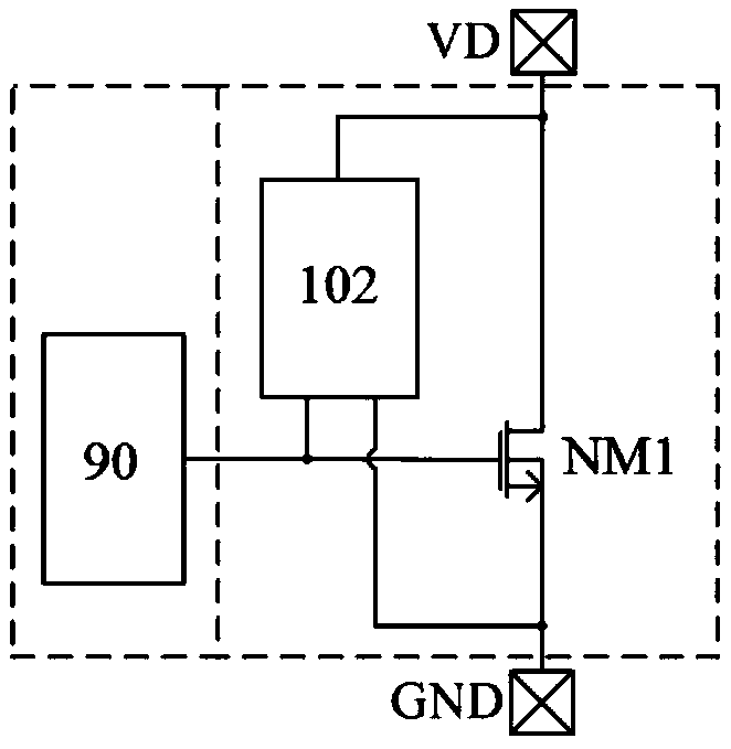
[0041] Figure 4 It is a schematic circuit diagram of an electrostatic discharge self-protection circuit 100 according to the first embodiment of the present invention, including an integrated power tube unit 101 and an auxiliary trigger circuit 102 .

[0042] The integrated power transistor unit 101 includes a power transistor NM1 , a drain pin VD and a ground pin GND. The power transistor NM1 is an N-channel MOS transistor and consists of several unit MOS transistors connected in parallel. The power tube NM1 is a power switch tube, which is the main MOS tube used in the power circuit of the power supply; and because the main function of the power tube in the power circuit is switching, it can also be referred to as a switch tube for short. The power switch tube, power tube or switch tube mentioned in this article all refer to this kind of MOS tube with the characteristics of large area, small conduction internal resistance and strong overcurrent capability. The drain of the...

no. 2 example

[0048] Figure 5 It is a schematic circuit diagram of an electrostatic discharge self-protection circuit 200 according to the second embodiment of the present invention, including an integrated power tube unit 101 and an auxiliary trigger circuit 202 . The difference from the first embodiment is that the auxiliary trigger circuit 202 of the second embodiment is composed of an NPN transistor B2 and a resistor R1. The collector of the NPN transistor B2 is connected to the drain of the power transistor NM1, the emitter of the transistor B2 is connected to the gate of the power transistor NM1, the base of the transistor B2 is connected to one end of the resistor R1, and the other end of the resistor R1 is connected to the power source of tube NM1.

[0049] Attached below Figure 5 Let me introduce, when a positive ESD event occurs at the VD terminal, the auxiliary trigger circuit 202 assists the power transistor to trigger and turn on the principle and working process of drain E...

no. 3 example

[0053] Image 6 It is a schematic circuit diagram of an electrostatic discharge self-protection circuit 300 according to the third embodiment of the present invention, including an integrated power tube unit 101 and an auxiliary trigger circuit 302 . For the electrostatic discharge self-protection circuits of the first and second embodiments, the power transistor NM1 is a high-voltage MOS transistor. As long as the appropriate NM2 and B2 devices are selected, the auxiliary trigger circuits provided by the auxiliary trigger circuits 102 and 202 can be applied to various switches The ESD protection trigger of the drain of the high-voltage switch tube is integrated in the power control chip, including the situation that the maximum drain voltage VDmax of the power tube NM1 is greater than, less than or equal to the chip power supply voltage VDD.

[0054] For the case where the power transistor NM1 is a low-voltage MOS transistor and its maximum drain voltage VDmax is lower than t...


PUM


Abstract

An electrostatic discharge self-protection circuit comprises an integrated power tube unit; and the integrated power tube unit comprises a power tube NM1, the power tube NM1 is an N-channel MOS transistor and is formed by connecting a plurality of unit MOS transistors in parallel, the drain electrode of the power tube NM1 is led out to serve as a drain electrode pin of the integrated power tube unit, and the source electrode of the power tube NM1 is led out to serve as a ground pin GND of the integrated power tube unit. The electrostatic discharge self-protection circuit further comprises an auxiliary triggering circuit which is connected between the drain electrode and the gate electrode of the power tube NM1; and when the drain electrode pin of the power tube generates an ESD event, theauxiliary triggering circuit is switched on earlier than the power tube NM1 to generate a switch on current to establish a gate source voltage of the power tube NM1, therefore, the gate source voltageof the power tube NM1 can reach a threshold voltage of the MOS transistors, and then a plurality of unit MOS transistors forming the power tube NM1 can be all switched on. The power tube NM1 is usedfor reusing a switch on path of the power tube NM1 to discharge the electrostatic current generated by the ESD event.

Description

technical field [0001] The invention relates to an integrated circuit, in particular to an electrostatic discharge self-protection circuit and a self-protection method when an ESD event occurs at a drain pin of an integrated power transistor. Background technique [0002] The important trend of current electronic product development is high integration and low cost, and switching power supply is widely used in various electronic products due to its small size, light weight and high efficiency. Integrating the power switching tube in the power topology into the control chip is an important measure to improve the integration and reduce the cost of the switching power supply, and this technology has also been widely used. Among them, the power switch tube is the main MOS tube used in the power circuit of the power supply, often referred to as the power tube; and because the main function of the power switch tube in the power circuit is switching, it can also be referred to as t...

Claims


Application Information

Patent Timeline
Patent Type & Authority Applications(China)
IPC IPC(8): H03K17/081H03K17/687
CPCH03K17/08104H03K17/687
Inventor 周阿铖曾正球
Owner SHENZHEN NANYUN MICROELECTRONICS CO LTD
Why Eureka
Try Eureka