
Welding mechanical arm capable of preventing sparks from splashing and working method of welding mechanical arm

A technology for welding machinery and robotic arms, applied in the field of intelligent robotic arms, can solve problems such as reducing the space of drive joints, and achieve the effects of eliminating inertia and sliding, ensuring production accuracy, and improving stability

Pending Publication Date: 2018-11-23
薛敏强
View PDF0 Cites 2 Cited by
  • Summary
  • Abstract
  • Description
  • Claims
  • Application Information

AI Technical Summary

Problems solved by technology

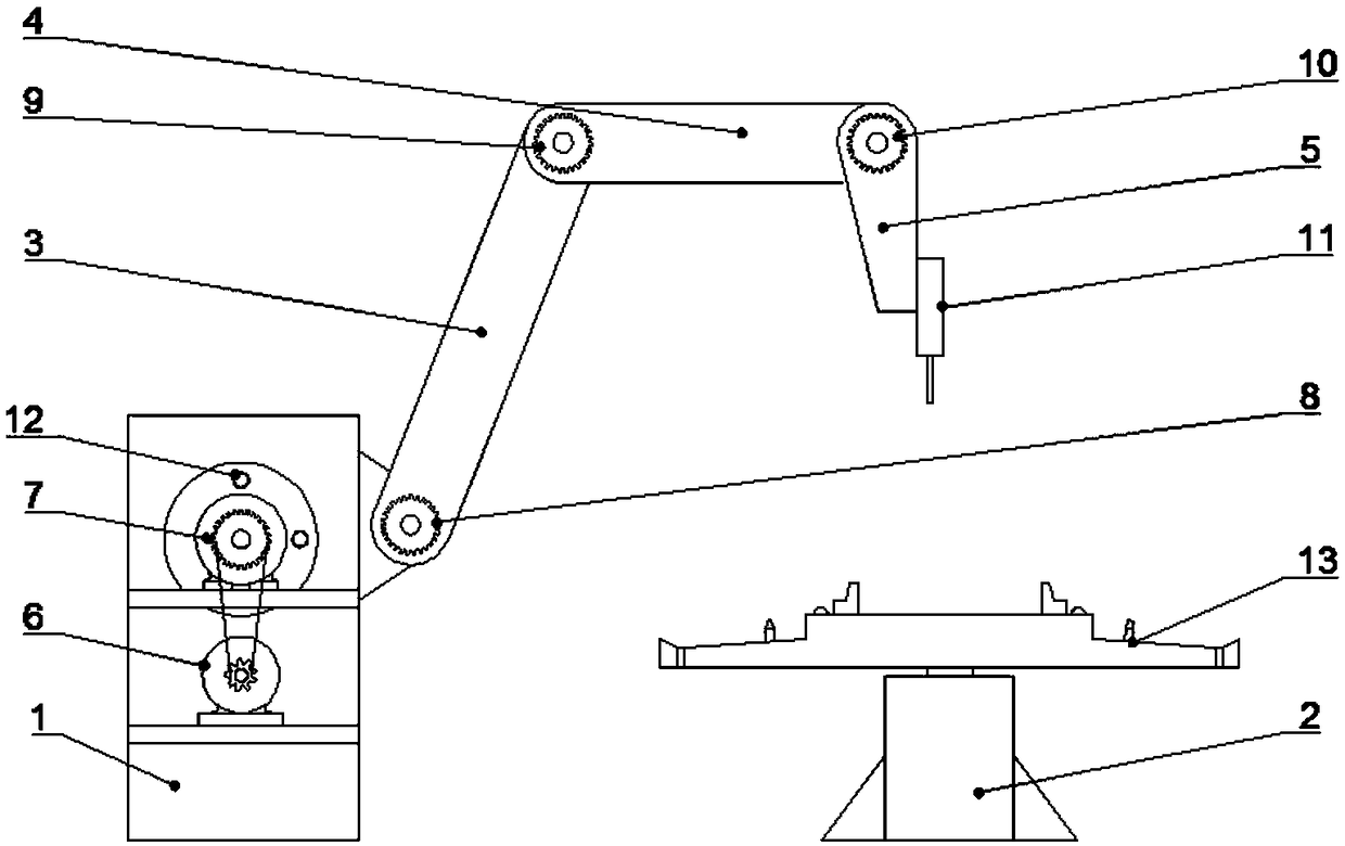
[0008] Purpose of the invention: In order to overcome the above deficiencies, the purpose of the present invention is to provide a spark spatter-proof welding mechanical arm and its working method. Solve the production problem, greatly improve the working efficiency of the manipulator, and at the same time realize the single motor drive, reduce the space required for the drive joint, reduce the cost of the driving parts, reduce the overall cost of the manipulator, and adapt to small batch production environment, so that it can be played in more fields

Method used


Image

  • Welding mechanical arm capable of preventing sparks from splashing and working method of welding mechanical arm
  • Welding mechanical arm capable of preventing sparks from splashing and working method of welding mechanical arm
  • Welding mechanical arm capable of preventing sparks from splashing and working method of welding mechanical arm

Examples


Embodiment 1

[0046] Such as figure 1 A spark spatter-proof welding robot arm is shown, including: a base 1, a rotating workpiece table 2, a first robot arm 3, a second robot arm 4, a third robot arm 5, a driving motor 6, and a transmission gearbox 7 , the first rotating sprocket group 8, the second rotating sprocket group 9, the third rotating sprocket group 10 and the end welding torch 11, the base 1 side is provided with a rotary table 2, and the base 1 upper end is provided with There is a first mechanical arm 3, the base 1 is hinged to the first mechanical arm 3, and one end of the first mechanical arm 3 is provided with a second mechanical arm 4, and the first mechanical arm 3 is hinged to the second mechanical arm 4 , one end of the second mechanical arm 4 is provided with a third mechanical arm 5, the second mechanical arm 4 is hinged with the third mechanical arm 5, and one end of the third mechanical arm 5 is fixed with a terminal welding torch 11; the base 1 is provided with a d...

Embodiment 2

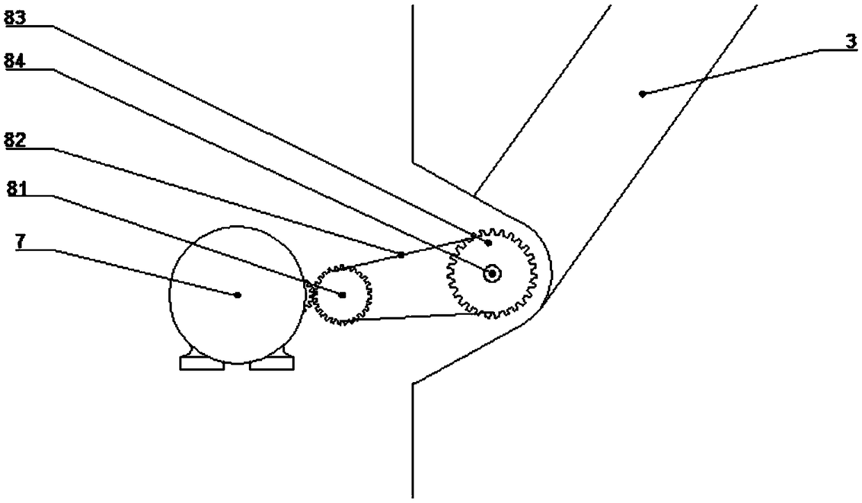
[0064] Such as figure 2 A spark spatter-proof welding robot arm is shown, including: a base 1, a rotating workpiece table 2, a first robot arm 3, a second robot arm 4, a third robot arm 5, a driving motor 6, and a transmission gearbox 7 , the first rotating sprocket group 8, the second rotating sprocket group 9, the third rotating sprocket group 10 and the end welding torch 11, the base 1 side is provided with a rotary table 2, and the base 1 upper end is provided with There is a first mechanical arm 3, the base 1 is hinged to the first mechanical arm 3, and one end of the first mechanical arm 3 is provided with a second mechanical arm 4, and the first mechanical arm 3 is hinged to the second mechanical arm 4 , one end of the second mechanical arm 4 is provided with a third mechanical arm 5, the second mechanical arm 4 is hinged with the third mechanical arm 5, and one end of the third mechanical arm 5 is fixed with a terminal welding torch 11; the base 1 is provided with a ...

Embodiment 3

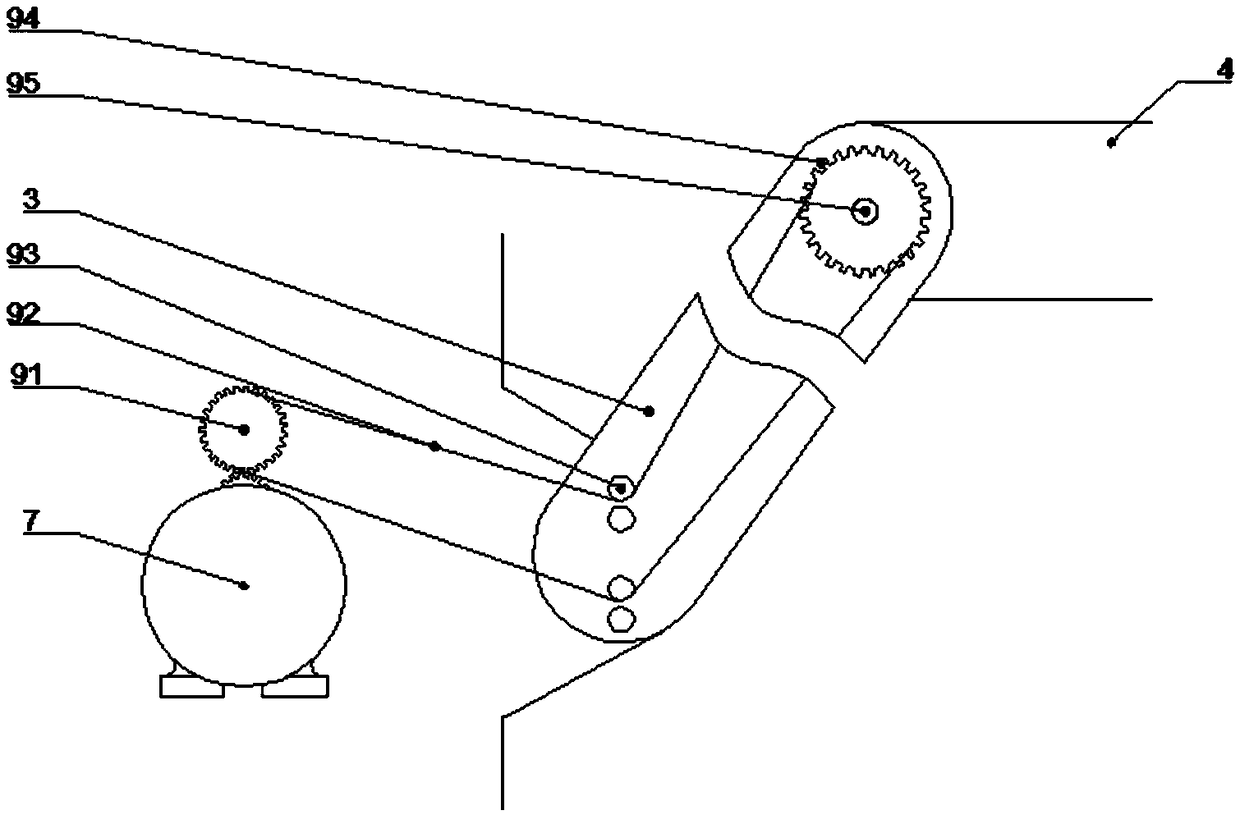
[0067] Such as image 3 A spark spatter-proof welding robot arm is shown, including: a base 1, a rotating workpiece table 2, a first robot arm 3, a second robot arm 4, a third robot arm 5, a driving motor 6, and a transmission gearbox 7 , the first rotating sprocket group 8, the second rotating sprocket group 9, the third rotating sprocket group 10 and the end welding torch 11, the base 1 side is provided with a rotary table 2, and the base 1 upper end is provided with There is a first mechanical arm 3, the base 1 is hinged to the first mechanical arm 3, and one end of the first mechanical arm 3 is provided with a second mechanical arm 4, and the first mechanical arm 3 is hinged to the second mechanical arm 4 , one end of the second mechanical arm 4 is provided with a third mechanical arm 5, the second mechanical arm 4 is hinged with the third mechanical arm 5, and one end of the third mechanical arm 5 is fixed with a terminal welding torch 11; the base 1 is provided with a d...


PUM


Abstract

The invention discloses a welding mechanical arm capable of preventing sparks from splashing. The welding mechanical arm comprises a base, a rotary workbench, mechanical arms, a drive motor, a transmission gear box, rotary chain wheel sets and a tail end welding gun. The rotary workbench is arranged on one side of the base. The mechanical arms are arranged at the upper end of the base, and the tail end welding gun is fixed to one end of one mechanical arm. The drive motor and the transmission gear box are arranged in the base. The rotary chain wheel sets are arranged at the hinged positions ofthe base and the mechanical arms. One end of the transmission gear box is connected with the rotary chain wheel sets. The invention further discloses a working method of the welding mechanical arm capable of preventing the sparks from splashing. The problem that personnel cannot approach to the mechanical arm due to the fact that sparks splash is solved; production problems can be found and handled in time in the work process; the work efficiency of the mechanical arm is improved; meanwhile, single motor drive is achieved; the space needed by a drive joint is reduced; the cost of a drive component is reduced; and the welding mechanical arm can adapt to the small-batch production environment and can be achieved in more fields.

Description

technical field [0001] The invention belongs to the field of intelligent mechanical arms, and in particular relates to a spark spatter-proof welding mechanical arm and a working method thereof. Background technique [0002] The continuous development of modern science and technology has greatly promoted the intersection and penetration of different disciplines, leading to technological revolution and transformation in the engineering field. The mechanical arm is a new technology emerging in the field of modern automatic control, and has become an important part of the modern mechanical manufacturing production system. This new technology developed rapidly, and gradually formed a new discipline - manipulator engineering. The mechanical arm is an important automation device that appeared in the late 1950s and has developed rapidly in recent years. It has now become an important means of industrial automation. Although the mechanical arm is not as flexible as the human hand a...

Claims


Application Information

Patent Timeline
Patent Type & Authority Applications(China)
IPC IPC(8): B23K37/02B23K37/00
CPCB23K37/00B23K37/0252
Inventor 薛敏强
Owner 薛敏强
Learn More